Thrust ball bearing ring end surface groove grinding method and device

A technology of thrust ball bearings and end faces, which is applied in the direction of abrasive surface adjustment devices, grinding workpiece supports, and parts of grinding machine tools. It can solve problems affecting machining accuracy and production efficiency, and complex grinding wheel dressing operations, so as to improve grinding wheel dressing. Accuracy, reduction of auxiliary time, and improvement of swing accuracy

Active Publication Date: 2017-06-16
浙江盛达智能装备有限公司
View PDF5 Cites 0 Cited by
  • Summary
  • Abstract
  • Description
  • Claims
  • Application Information

AI Technical Summary

Problems solved by technology

[0003] The purpose of the present invention is to overcome the defects that the existing grinding wheel dressing operation of the end surface groove grinding of the thrust ball bearing ring is complicated, and it is easy to affect the processing accuracy and production efficiency, and to provide a thrust ball bearing ring with good precision and high production efficiency Face groove grinding method and device thereof

Method used


Image

  • Thrust ball bearing ring end surface groove grinding method and device
  • Thrust ball bearing ring end surface groove grinding method and device
  • Thrust ball bearing ring end surface groove grinding method and device

Examples


Embodiment Construction

[0020] Specific embodiments of the present invention will be described in detail below in conjunction with the accompanying drawings.

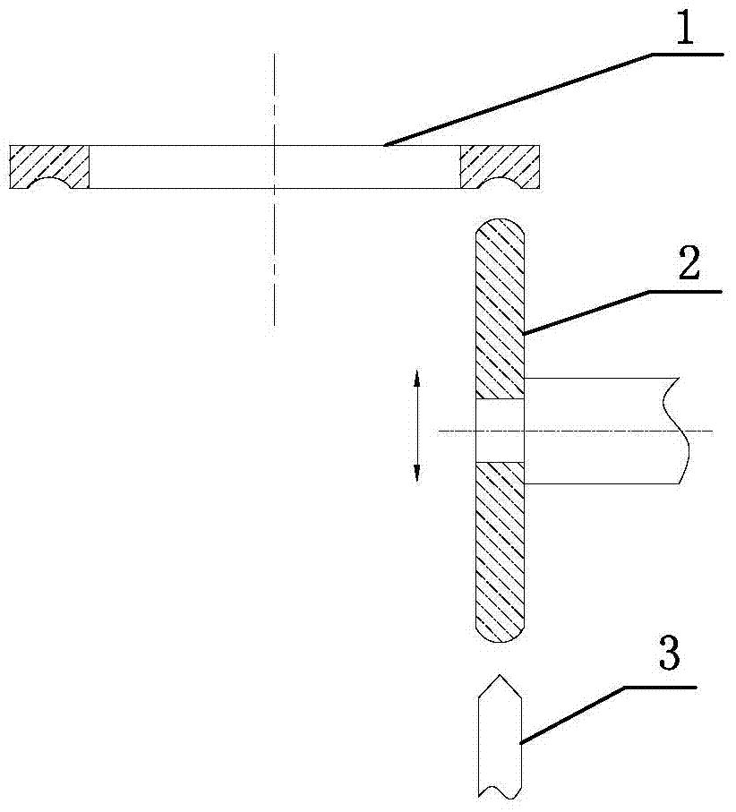
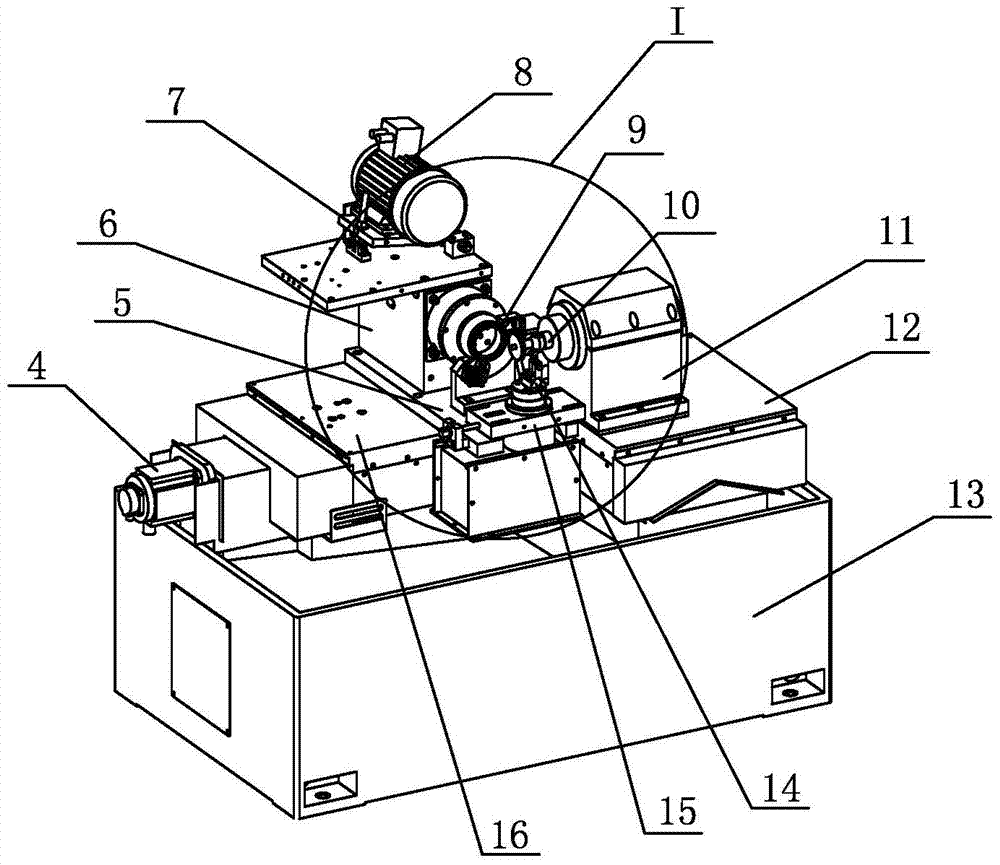
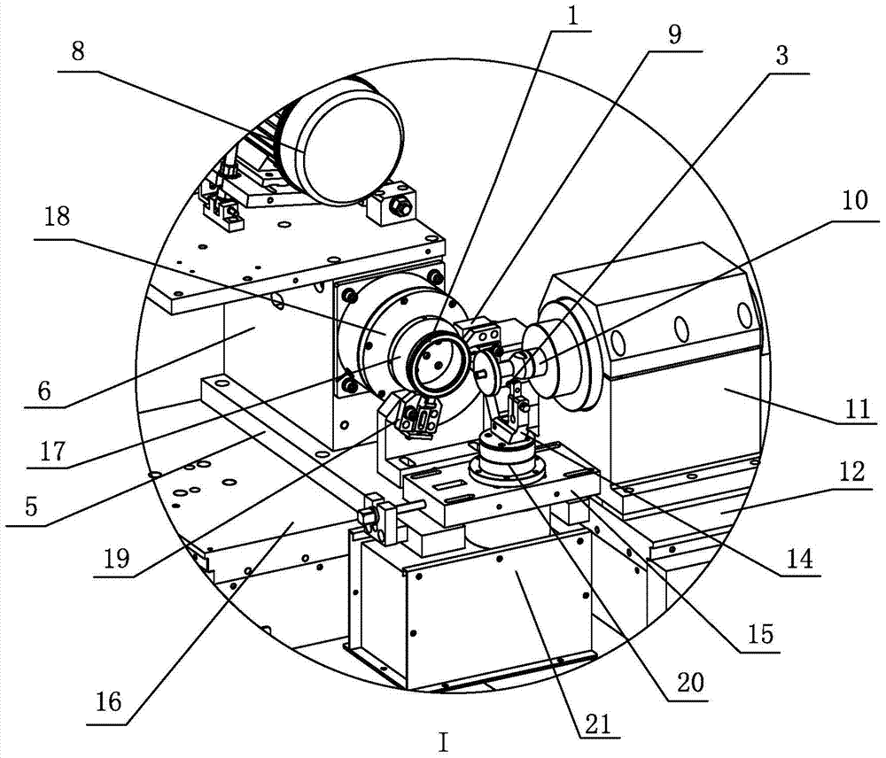
[0021] Such as figure 1 As shown, in the method of the present invention, the ferrule of the thrust ball bearing is clamped by the clamping mechanism on the workpiece spindle 18 with the center line in a transverse state, and the forming disc type grinding wheel 2 with the outer circular surface as the arc surface is used as the grinding tool , the ferrule 1 rotates with its own center line as the center of rotation, the center line of the grinding wheel 2 is perpendicular to the center line of the ferrule 1, the grinding wheel 2 rotates at a high speed and its arc outer surface is tangent to the groove of the end face of the ferrule In contact, the trimming pen 3 for circular arc swinging motion is arranged in front of the workpiece spindle 18 to trim the shape of the grinding wheel 2. On one plane, the grinding wheel 2 only moves in a strai...


PUM


Abstract

The invention provides a thrust ball bearing sleeve ring end surface groove grinding method and a device realizing the method, and belongs to the technical field of bearing sleeve ring processing. According to the method provided by the invention, a grinding wheel trimming pen is arranged in the feeding direction of a grinding cutter, when a bearing sleeve ring is replaced, the grinding cutter returns until the grinding cutter is abutted against the pen point part of the grinding wheel trimming pen, and the grinding wheel trimming pen trims the grinding cutter. The device for realizing the method comprises a machine body, a workpiece main shaft device, a grinding wheel device, a grinding wheel feeding mechanism and a grinding wheel trimming device, wherein the workpiece main shaft device drives the bearing sleeve ring to rotate, the grinding wheel device is positioned between the bearing sleeve ring and the grinding wheel trimming device and drives a circular disc type grinding wheel to rotate at a high speed, the trimming pen of the grinding wheel trimming device performs swinging rotation along a swinging rotation track corresponding to the groove circular arc of the bearing sleeve ring through being driven by the motor, and the grinding wheel returns back onto the trimming pen for trimming during the bearing sleeve ring replacement. The method and the device provided by the invention solve the problems that the grinding wheel trimming operation of the existing thrust ball bearing sleeve ring end surface groove grinding is complicated, and the processing precision and the production efficiency can be easily influenced.

Description

technical field [0001] The invention belongs to the technical field of bearing ring processing, and in particular relates to a method and a device for grinding the end surface groove of a thrust ball bearing ring. Background technique [0002] The end surface groove of the thrust ball bearing ring is an arc-shaped groove, and the intersection line between the end surface groove and the longitudinal section passing through the center line of the ring is an arc line. After the end surface groove is formed by cutting, it needs to be ground to improve the precision of the groove. The existing grinding machines used for grinding the grooves of the end faces of thrust ball bearing rings all adopt the workpiece spindle device fixed on the top surface of the bed, the grinding wheel dresser is set at a position away from the workpiece spindle, and the grinding wheel spindle is controlled by the X-axis, Y-axis The feed mechanism with axes crossed and stacked is driven to move in the ...

Claims


Application Information

Patent Timeline
Patent Type & Authority Patents(China)
IPC IPC(8): B24B19/06B24B53/065B24B53/12
CPCB24B19/06B24B41/04B24B41/06B24B53/065B24B53/12
Inventor 王国勇俞伟锋
Owner 浙江盛达智能装备有限公司
Why Eureka
Try Eureka