
Clamping device capable of adapting to cylindrical workpieces with different outer diameter sizes

An outer diameter size, adaptable to different technologies, applied in the field of robots, can solve the problems of not meeting the requirements of forging robotic arms, reducing production efficiency, increasing auxiliary time and production cost, etc., to achieve simple structure, improve production efficiency, and reduce auxiliary time. Effect

Inactive Publication Date: 2018-12-21
QINGDAO UNIV +1
View PDF10 Cites 15 Cited by
  • Summary
  • Abstract
  • Description
  • Claims
  • Application Information

AI Technical Summary

Problems solved by technology

[0003] Since the forging manipulator faces workpieces of various specifications and sizes in the actual use process, it is not feasible to use the same gripper to complete all the work. The current common method is to replace different manipulator arm grippers according to different workpiece sizes. However, this will inevitably increase auxiliary time and production costs, and reduce production efficiency. 201620294351.2 discloses a mechanical arm gripper with self-adaptive capabilities, including a lower base and an upper base; the lower base is provided with a driving device; the upper base There are two opposite mounting plates on the top, and two clamping components are fixed on the mounting plate; the driving device includes a motor fixed in the lower base, and a gear set connected to the motor; the clamping component includes a motor connected to the two mounting plates The drive shaft that matches the gear set between them, and the gear shaft that is connected between the two mounting plates and matches the drive shaft; the drive shaft and the gear shaft are arranged side by side; the left clamp arm is connected to the gear shaft, and the transmission The right clamping arm is connected to the shaft, which has a certain self-adaptive ability. With the reasonable cooperation of the clamping arm, the spring and the drive motor, it can clamp and move various types of objects, such as the basic shape of a rectangular parallelepiped and a circular cross section. Objects and irregular-shaped objects containing holes with a certain inner diameter; 201720434338.7 discloses an adaptive automatic manipulator structure, including a position slide on the manipulator, and a two-way hydraulic cylinder is provided on the side of the position slide away from the manipulator. The two output ends of the two-way hydraulic cylinder are fixedly connected with push rods, and the two push rods are arranged opposite to each other. The position slide table is provided with a chute corresponding to the push rods. The end of the side away from the inner bottom of the chute is provided with a first telescopic rod, and the side of the two-way hydraulic cylinder away from the position slide table is fixedly connected with a support block, and the support block is connected with two staggered clamps through the first rotating shaft. One of the clamping handles is fixedly connected to the first rotating shaft, and the other is rotatably connected to the first rotating shaft, which has a simple structure and is easy to operate, and is simultaneously clamped by a multi-directional clamping mechanism, which improves the stability of the device. Gripping capacity for increased plant productivity
However, the above-mentioned mechanical arm gripper cannot meet the requirements of the forging mechanical arm for the gripper

Method used


Image

  • Clamping device capable of adapting to cylindrical workpieces with different outer diameter sizes
  • Clamping device capable of adapting to cylindrical workpieces with different outer diameter sizes
  • Clamping device capable of adapting to cylindrical workpieces with different outer diameter sizes

Examples


Embodiment

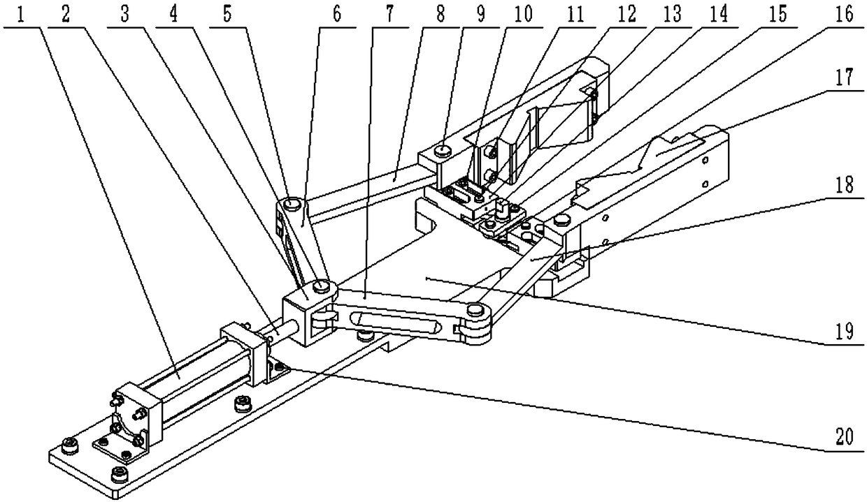
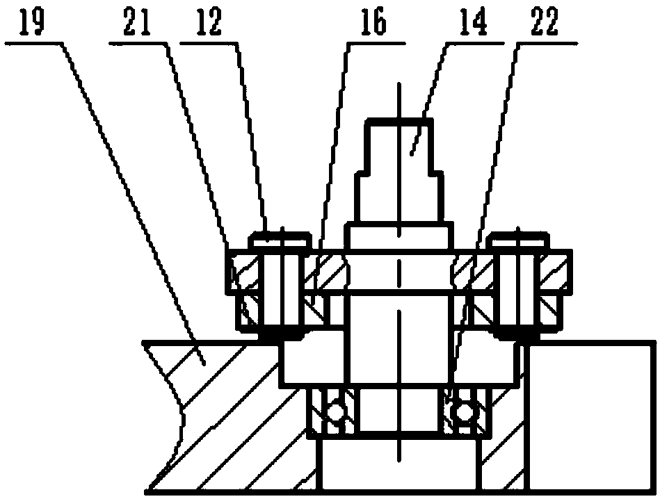
[0016] The main structure of the mechanical arm gripper described in this embodiment includes a clamping hydraulic cylinder 1, a clamping hydraulic cylinder piston rod 2, a joint 3 for clamping the hydraulic cylinder, a pin shaft 4 for the joint, and a pin shaft for the connecting rod 5. Left connecting rod 6, right connecting rod 7, left clamping arm 8, pin shaft 9 for clamping arm, hexagon socket screw 10 for slider, hexagon socket screw 11 for clamping block, sliding Block pin 12, slider 13, crank shaft 14, pin 15 for small connecting rod, small connecting rod 16, V-shaped clamping block 17, right clamping arm 18, support plate 19, clamping hydraulic pressure Screws 20 for the cylinder, circlips 21 for the shaft, deep groove ball bearings 22, hexagonal thin nuts 32 for the clamping hydraulic cylinder; the front and rear foot type clamping hydraulic cylinders 1 are fixedly connected by the screws 20 for clamping the hydraulic cylinder On the steel support plate 19, the clamp...


PUM


Abstract

The invention belongs to the technical field of robots, and relates to a forging mechanical arm clamping device capable of adapting to cylindrical workpieces with different outer diameter sizes. A clamping hydraulic cylinder is adopted to drive a piston rod of the clamping hydraulic cylinder to move in a reciprocating mode, the piston rod of the clamping hydraulic cylinder is driven by a left sideconnecting rod and a right side connecting rod and is used for converting the reciprocating movement of the piston rod of the clamping hydraulic cylinder into reciprocating swinging of a left clamping arm and a right clamping arm around fixing hinge points, and the workpiece is clamped and loosened through V-shaped clamping blocks arranged on the clamping arms; and the two sliding blocks in two long slotted holes are loosened, and when inner hexagonal screws are used for the two sliding blocks in the two long slotted holes, and the positions of the sliding blocks in slide ways of supporting plates can be changed by rotating crank shafts, so that the positions of the fixing hinge points of the left clamping arm and the right clamping arm are changed, and the cylindrical workpieces with different outer diameter sizes can be clamped. The forging mechanical arm clamping device is reliable in principle, simple in structure, convenient to operate, good in environmental adaptability, and safe and reliable, and can complete the clamping tasks of the workpieces with different outer diameters without replacing the clamping device.

Description

Technical field: [0001] The invention belongs to the technical field of robots, and relates to a clamper for a forging mechanical arm that can adapt to cylindrical workpieces with different outer diameters. The cylindrical workpiece with outer diameter improves the working efficiency of the manipulator and maintains good mechanical properties of the forging manipulator gripper. technical background: [0002] Forging production is affected by adverse factors such as high temperature, vibration, noise, etc., the working environment is poor, and the labor intensity is high. It is urgent to realize the mechanization and automation of the production process. With the development and growth of the forging industry, the current production status of traditional large-scale free forging equipment such as scattered layout, low utilization rate, and low degree of mechanization and automation has been unable to meet its development requirements. As an automation device that can imitate...

Claims


Application Information

Patent Timeline
Patent Type & Authority Applications(China)
IPC IPC(8): B21J13/10
Inventor 张继忠张钊田仲华赵梅
Owner QINGDAO UNIV
Learn More