Elevator cable swing suppression system
A cable and elevator technology, applied in the field of elevator cable swing suppression system, can solve problems such as difficulty in suppressing cable swing
- Summary
- Abstract
- Description
- Claims
- Application Information
AI Technical Summary
Problems solved by technology
Method used
Image
Examples
no. 1 Embodiment approach )
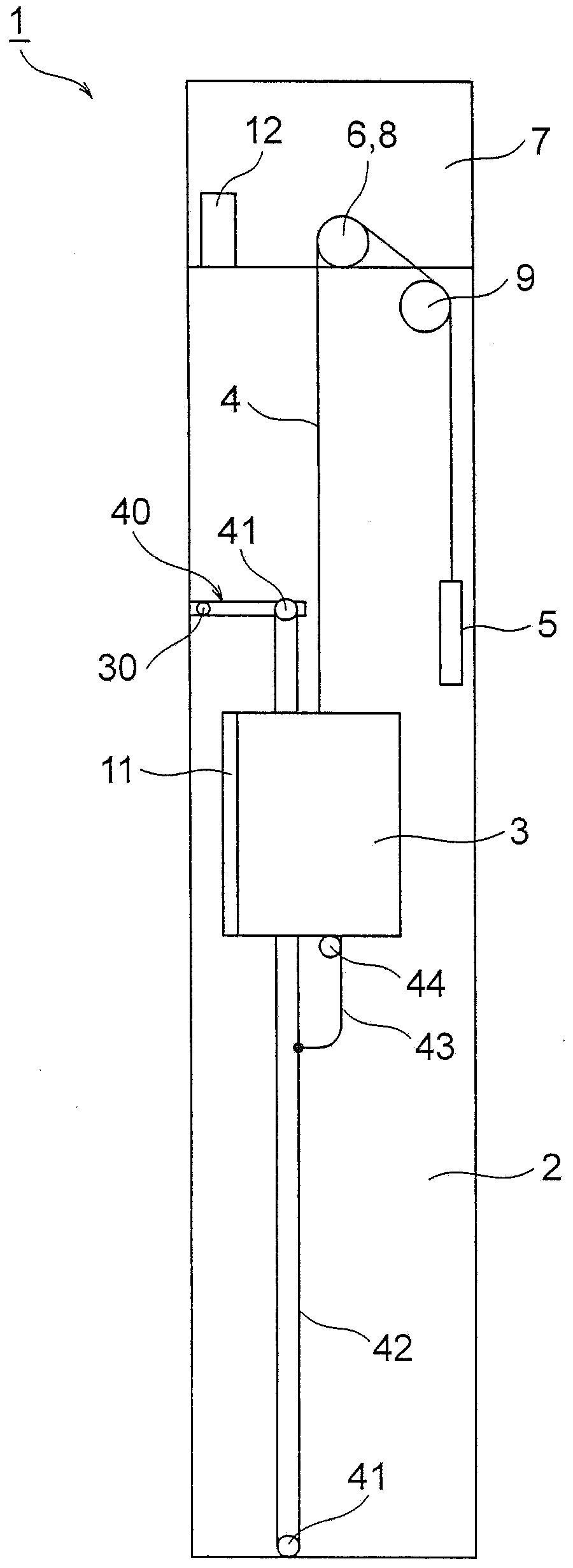
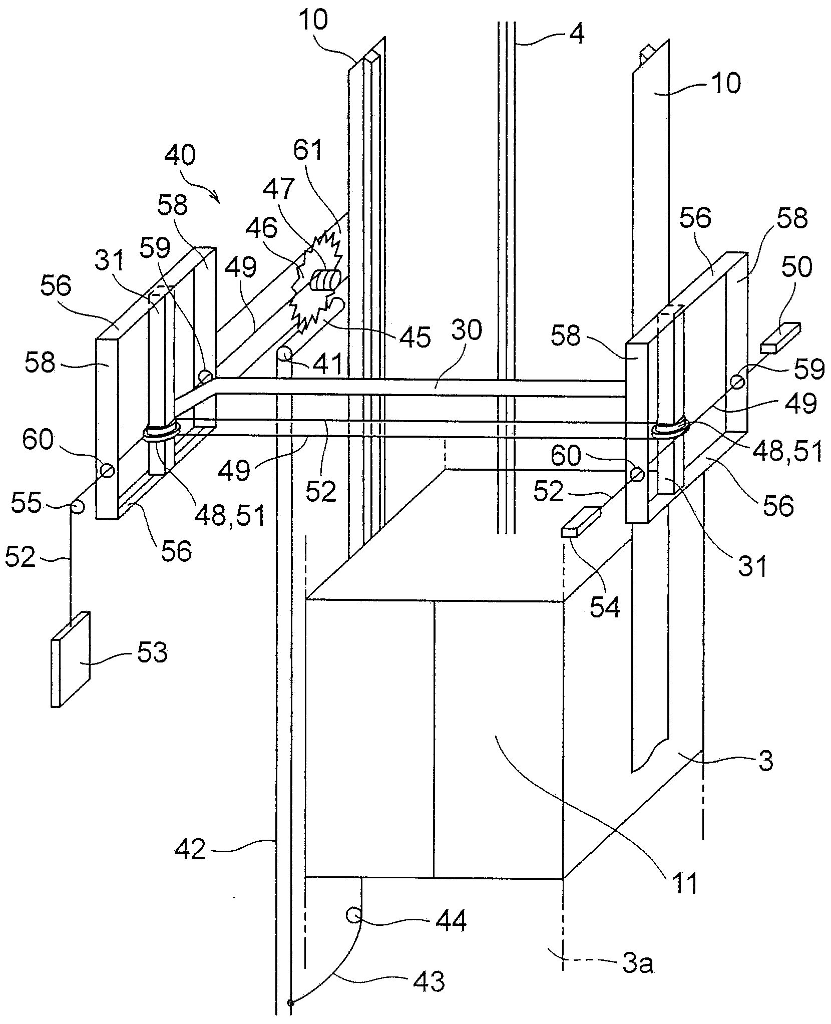
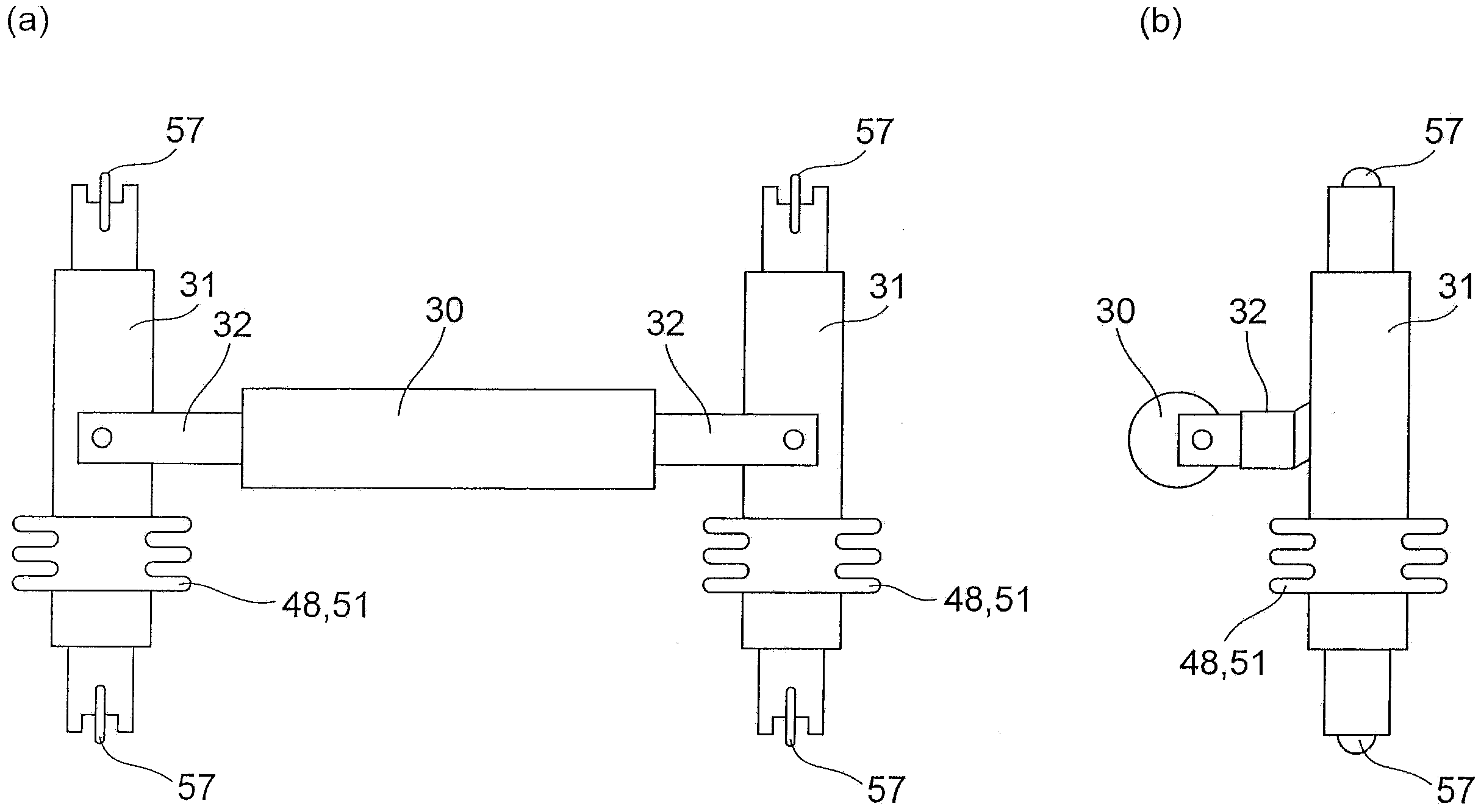
[0031] use Figure 1 to Figure 3 , the elevator rope swing suppression system according to the first embodiment of the present invention will be described.
[0032] Here, first, the elevator apparatus to which the elevator rope swing suppression system of this embodiment is applied is demonstrated. Such as figure 1 As shown, the elevator device 1 is provided with: a car 3, which can freely ascend and descend in the hoistway 2; a counterweight 5 for the car, which is connected to the car 3 via a main cable 4; and a traction machine (lifting drive part) 6 , which raises and lowers the car 3 and the counterweight 5 for the car via the main rope 4 . Among them, the hoisting machine 6 is disposed in a machine room 7 provided above the hoistway 2 . The main rope 4 is wound around a traction sheave (pulley) 8 and a guide sheave 9 connected to the hoisting machine 6 .
[0033] In such a configuration, the hoisting machine 6 rotationally drives the hoisting sheave 8, the main rope ...
no. 2 Embodiment approach )
[0057] Next, according to Figure 4 to Figure 7 , an elevator rope swing suppression system according to a second embodiment of the present invention will be described.
[0058] exist Figure 4 to Figure 7 In the second embodiment shown, the main difference is that the swing suppressing member is moved in the front-rear direction by the winding motor, and the swing suppressing member moves rearward according to the positional relationship between the swing suppressing member and the car. Other composition and Figure 1 to Figure 3 The first embodiment shown is substantially the same. In addition, in Figure 4 to Figure 7 in, right with Figure 1 to Figure 3 The parts that are the same as those in the first embodiment shown are given the same reference numerals, and detailed descriptions thereof will be omitted.
[0059] Such as Figure 4 as well as Figure 5 As shown, the swing suppressing member 30 is moved in the front-rear direction by the winding motor (winding driv...
no. 3 Embodiment approach )
[0081] Next, pass Figure 8 to Figure 10 , the elevator rope swing suppression system in the third embodiment of the present invention will be described.
[0082] exist Figure 8 to Figure 10 In the third embodiment shown, the main difference is that a plurality of swing restraining members are provided at positions different from each other in the lifting direction of the car, and the other configurations are the same as those of the third embodiment. Figure 4 to Figure 7 The second embodiment shown is substantially the same. In addition, in Figure 8 to Figure 10 in, right with Figure 4 to Figure 7 The parts that are the same as those in the second embodiment shown are given the same reference numerals, and detailed descriptions thereof will be omitted.
[0083] Such as Figure 8 As shown, a plurality of (here, two) swing suppressing members 30 ( 30 a , 30 b ) are provided at positions different from each other in the ascending and descending direction of the car 3 . ...
PUM
 Abstract
Description
Claims
Application Information
 - R&D
- Intellectual Property
- Life Sciences
- Materials
- Tech Scout
- Unparalleled Data Quality
- Higher Quality Content
- 60% Fewer Hallucinations
Browse by: Latest US Patents, China's latest patents, Technical Efficacy Thesaurus, Application Domain, Technology Topic, Popular Technical Reports.
© 2025 PatSnap. All rights reserved.Legal|Privacy policy|Modern Slavery Act Transparency Statement|Sitemap|About US| Contact US: help@patsnap.com


