
Panel device of strongbox cabinet

A technology of panels and cabinets, which is applied in the direction of safes, buildings, building structures, etc., can solve the problems of heavy hand feeling and laborious use, and achieve the effects of good concealment, convenient use, and convenient assembly

Inactive Publication Date: 2015-01-14
NINGBO AIPU IND
View PDF5 Cites 0 Cited by
  • Summary
  • Abstract
  • Description
  • Claims
  • Application Information

AI Technical Summary

Problems solved by technology

However, the power part for opening the electronic lock panel in the above structure adopts the fork on the traditional mechanical lock cylinder, and the mechanical lock cylinder needs to be opened with a key. If the key is lost, the panel cannot be opened; in addition, when in use, the key drives the rotation The driving mechanism feels too heavy, and it is laborious to use

Method used


Image

  • Panel device of strongbox cabinet
  • Panel device of strongbox cabinet
  • Panel device of strongbox cabinet

Examples


Embodiment 1

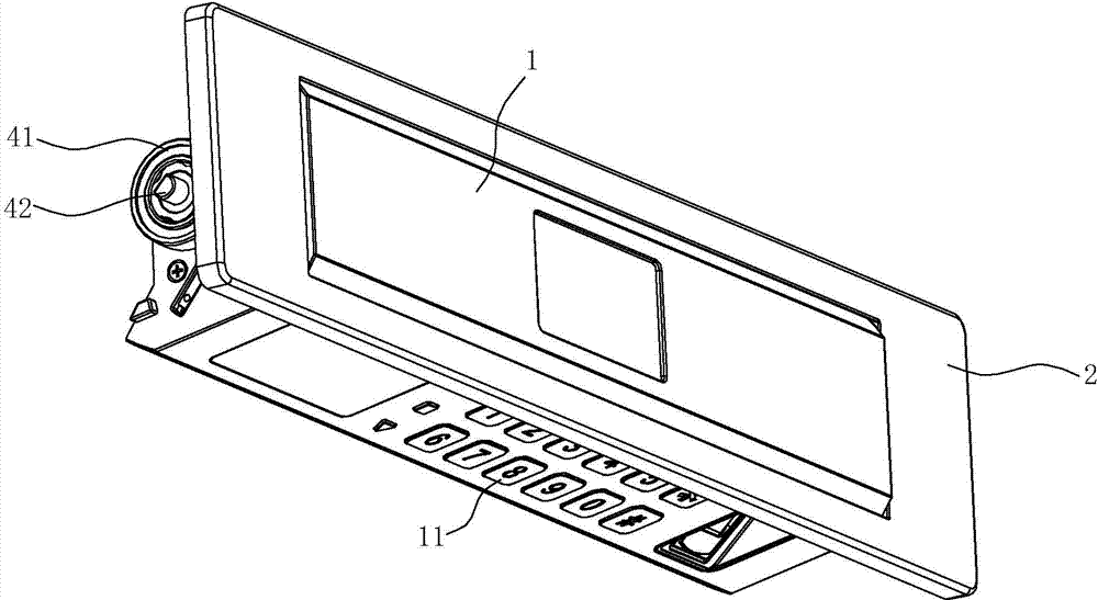
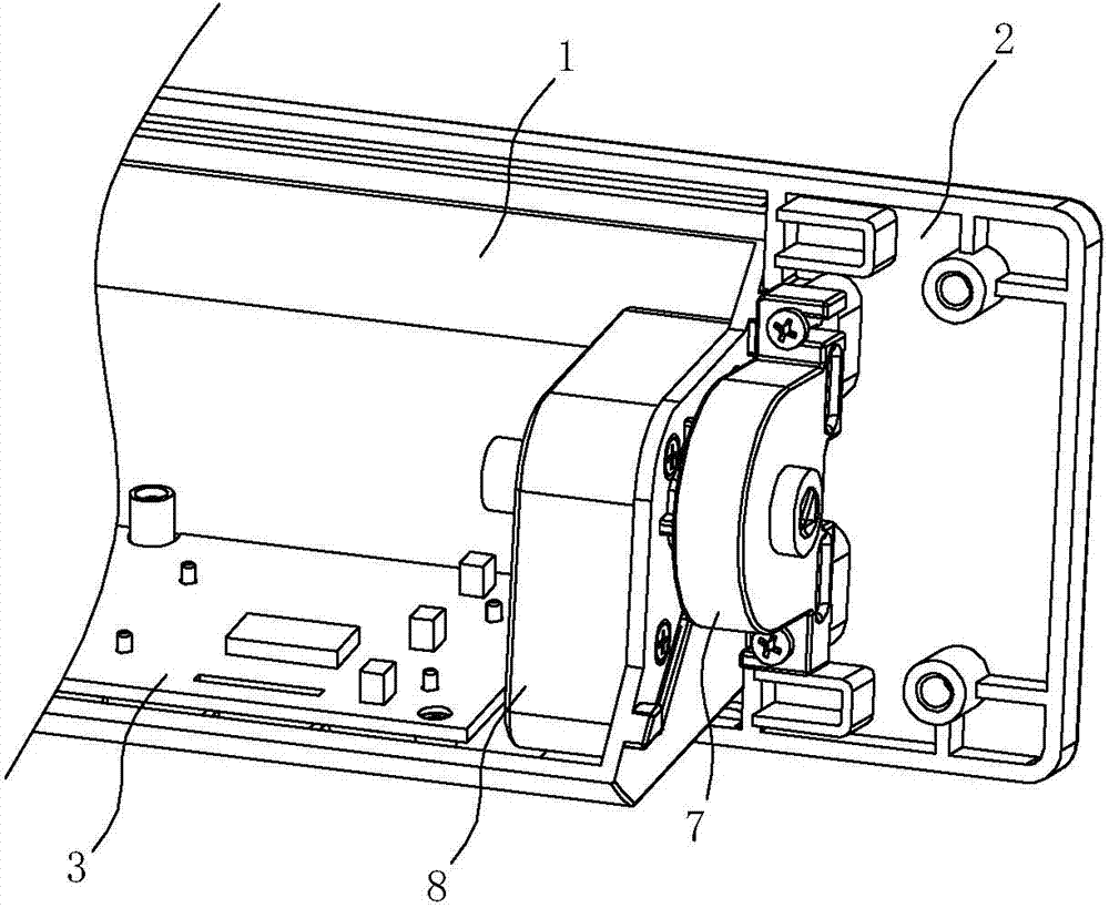
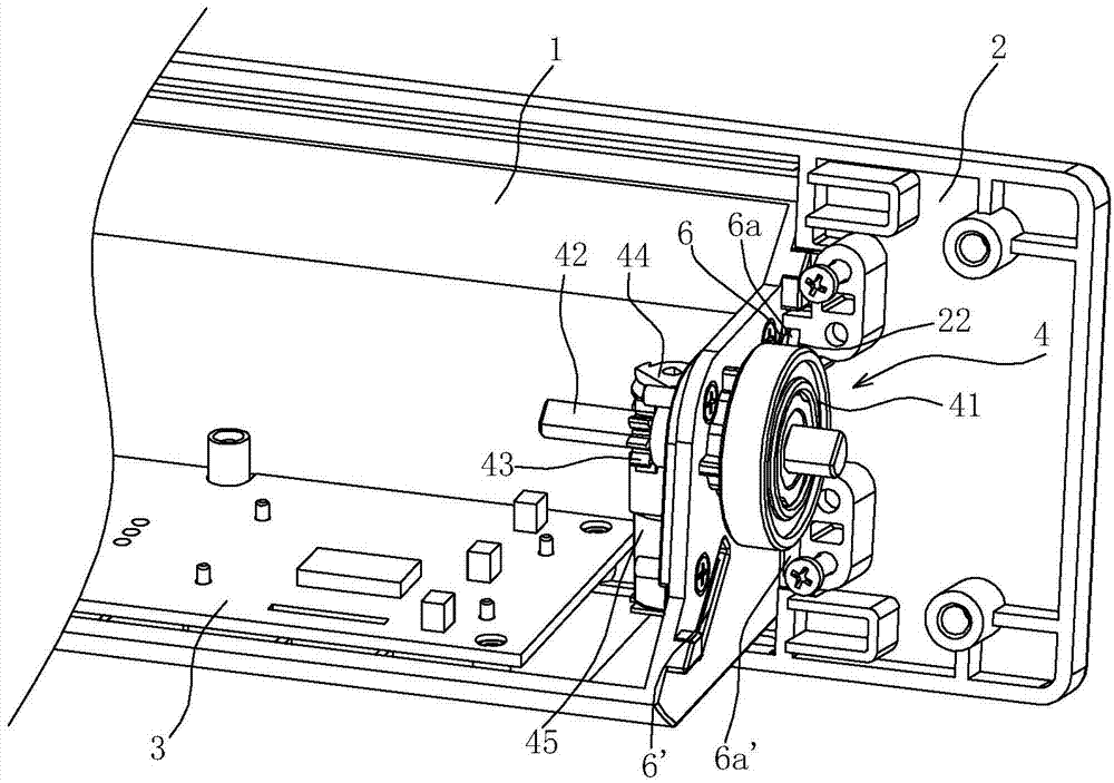
[0048] Such as Figure 1~4 As shown, the panel device of the safe cabinet of this embodiment includes a panel 1 and a panel fixing frame 2, the main body section of the panel 1 is in an "L" shape, and a control circuit board 3 is arranged on the inner side of the bottom of the panel 1, and the control circuit board 3 has The control circuit is generally made of a digital circuit of a microprocessor. A digital keypad 11 is arranged on the outer surface of the bottom of the panel 1. The digital keypad 11 is electrically connected to the control circuit board 3; The mounting opening 21 that matches the outer circumference of the panel 1 is generally consistent with the size and shape of the front of the panel 1. The panel 1 can be turned over and set inside the installation opening 21. When the panel 1 is turned outward by 90°, the outer surface of the bottom of the panel 1 The number keypad 11 is exposed on the side, and is on the same vertical plane as the panel fixing frame 2,...

Embodiment 2

[0054] The difference between this embodiment and embodiment 1 is: as Figure 5 , 6 As shown, what can trigger the panel 1 to turn inside out is the fingerprint collector 100 arranged on the outer surface of the front of the panel 1 and the digital keypad 11 arranged under the bottom of the panel 1, and the fingerprint collector 100 is electrically connected to the control circuit board 3 . During use, input the fingerprint on the fingerprint collector 100, if the input of the fingerprint is correct, the detection circuit is connected, and the microprocessor outputs an execution signal for flipping outwards, so that the motor 45 runs forward, and the panel 1 starts to open relative to the panel fixing frame 2; If the fingerprint input is wrong, then the detection circuit is disconnected; after using, press the hotkey on the number keypad 11 such as the meter key or the enter key, etc., and the microprocessor output in the control circuit is connected to the execution signal t...

Embodiment 3

[0056] The difference between this embodiment and embodiment 1 is: as Figure 7 , 8 As shown, what can trigger the panel 1 to turn inside and outside is the driving button 200 arranged on the front of the panel 1 or the outer surface of the panel fixing frame 2. The driving button 200 is electrically connected to the control circuit board 3. If the driving button 200 is arranged on the panel fixing frame 2 On the outer side of the frame 2, when in use, press the drive button 200, the detection circuit is connected, the microprocessor in the control circuit outputs an execution signal for turning outwards, and the motor 45 is run forward, and the panel 1 is fixed to the panel. 2. Start to open; after use, press the drive button 200 again, and the microprocessor connected to the control circuit will output an inward flip execution signal to make the motor 45 run in reverse, thereby driving the panel 1 to rotate inward, so that the panel 1 is relatively Start closing at panel fi...


PUM


Abstract

The invention relates to a panel device of a strongbox cabinet. The panel device comprises a panel fixing frame, a panel and a transmission mechanism, wherein the panel fixing frame is provided with an installing opening, the size and the shape of the front side of the panel are matched with those of the installing opening formed in the panel fixing frame, in addition, the panel is arranged at the inner side of the installing opening in a way of being capable of rotating, and the transmission mechanism is arranged at the inner side of the installing opening formed in the panel fixing frame and drives the panel to rotate. The panel device is characterized in that the transmission mechanism is a transmission mechanism adopting a motor for driving, and at least comprises the motor, a worm wheel, a worm rod and a control part, wherein the motor is fixedly arranged at the inner side of the panel, and is used as turning power, the worm wheel is directly or indirectly and transversely fixed on the panel fixing frame, the worm rod is longitudinally arranged at the inner side of the panel, one end of the worm rod is directly or indirectly and fixedly connected with an output shaft of the motor, the other end of the worm rod is engaged and connected with the worm wheel, and the control part controls the turning angle of the panel. The panel device has the advantages that better safety performance is realized, in addition, the structure is simple, and the assembling and the use are convenient.

Description

technical field [0001] The invention relates to the technical field of components of safe cabinets, in particular to a panel device of a safe cabinet, which is used for installing electronic lock components. Background technique [0002] The electronic lock panel of the existing safe or safe is generally directly installed on the door panel of the cabinet body, and the keyboard and display screen on the electronic lock panel are directly exposed to the outside. Illegal tentative opening is also easy to be damaged by impact, thereby affecting the normal use of the safe. Therefore, the concealment and the safety of the electronic lock panel of the safe cabinet need to be improved. [0003] The Chinese utility model patent "A Panel Device on a Safe Cabinet" (Application No.: 200820167899.6) with the authorized announcement number CN201297090Y discloses such a structure, which includes a door panel with a cabinet and a panel installed on the door panel, which is characterized i...

Claims


Application Information

Patent Timeline
Patent Type & Authority Applications(China)
IPC IPC(8): E05G1/02
CPCE05G1/02
Inventor 戴旭东
Owner NINGBO AIPU IND
Learn More