
Ranging method and device

A distance measurement method and distance technology, applied in the field of communication, can solve problems such as being easily affected by the environment, unable to perform real-time positioning, and data loss.

Active Publication Date: 2015-01-14
THE PLA INFORMATION ENG UNIV
View PDF7 Cites 10 Cited by
  • Summary
  • Abstract
  • Description
  • Claims
  • Application Information

AI Technical Summary

Problems solved by technology

[0003] At present, there are three commonly used positioning methods: the first is the global positioning system, but the system has high cost, high energy consumption, and is easily affected by the environment, so it is not suitable for deployment in a large-scale wireless communication network.
The second is the positioning method without ranging. This method only estimates the position of the node to be located based on the connection information between the node and the surrounding reference nodes. The uncertainty of the positioning error of this method is relatively large.
The third is the positioning method based on distance measurement. This method needs to complete the distance measurement service by sending and receiving the distance measurement packet. At present, the data communication service and the node positioning and distance measurement service are both carried on the data link layer. These two services interact with each other. Independent, unable to initiate two kinds of services at the same time, which will cause real-time positioning impossible due to the impact of data communication services; or due to the impact of ranging services, data communication services cannot be completed, for example, network monitoring or collected data may not be available Timely transmission to the control terminal, or cause data loss
In addition, for this ranging-based positioning method, sending and receiving ranging packets will occupy limited wireless broadband resources, and the sending of data will inevitably consume node energy

Method used


Image

  • Ranging method and device
  • Ranging method and device
  • Ranging method and device

Examples


Embodiment 1

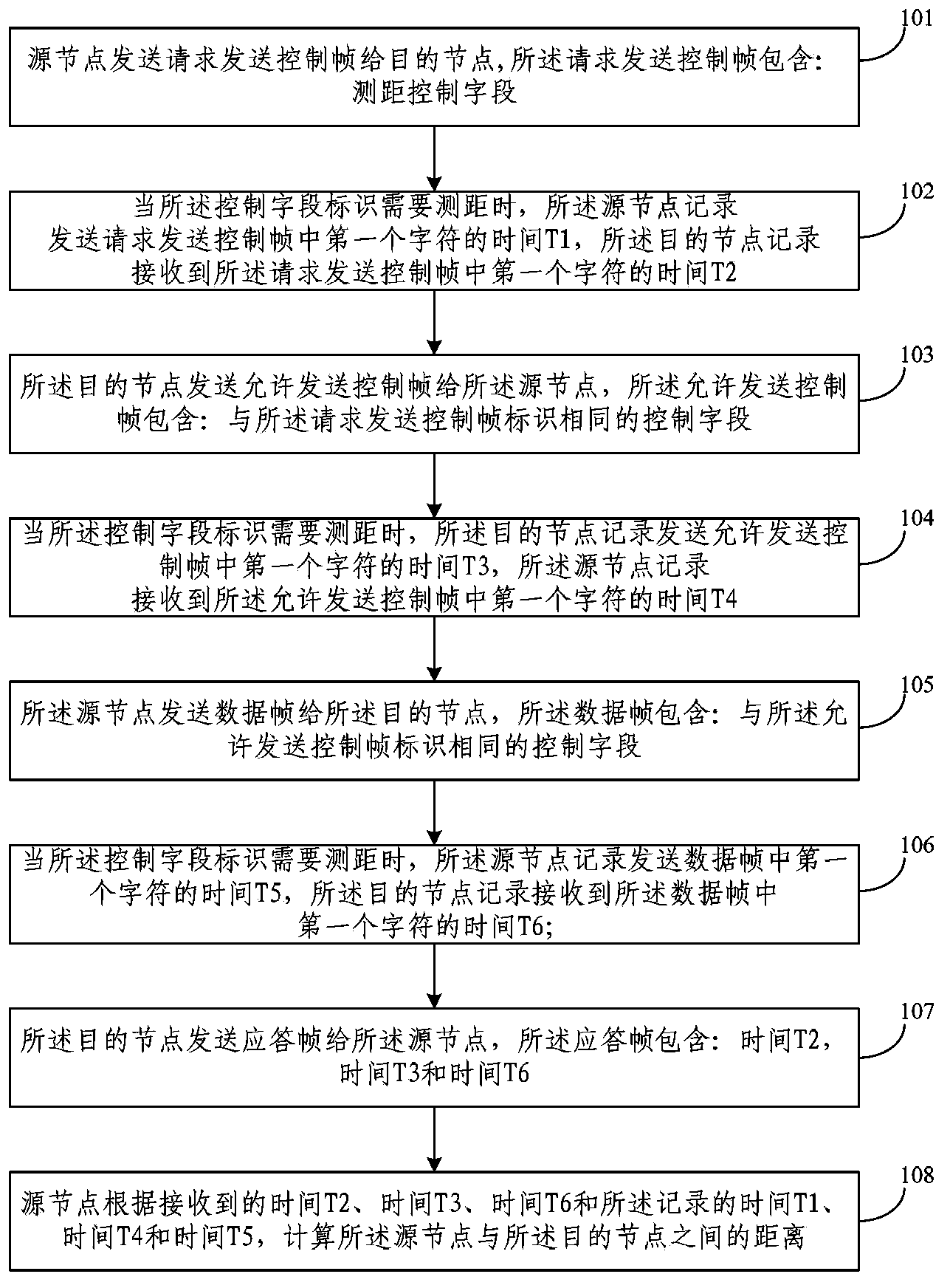
[0054] see figure 1 , which is a method flow chart of a ranging method disclosed in Embodiment 1 of the present application, and the method includes the following steps:

[0055] Step 101: the source node sends a request to send control frame to the destination node, the request to send control frame includes: a ranging control field, and the ranging control field is used to identify whether ranging is required;

[0056] The carrier sense multiple access / collision avoidance protocol (Carrier Sense Multiple Access with Collision Avoidance, CSMA / CA) in the wireless local area network standard 802.11, its working principle is:

[0057] Reserve the channel before sending the data frame. Specifically, when the source node A needs to send data to the destination node B, the source node A needs to send a request to send frame (Request To Send, RTS) to the destination node B before sending the data frame. The RTS frame includes: frame type, length of sent data, destination node addr...

Embodiment 2

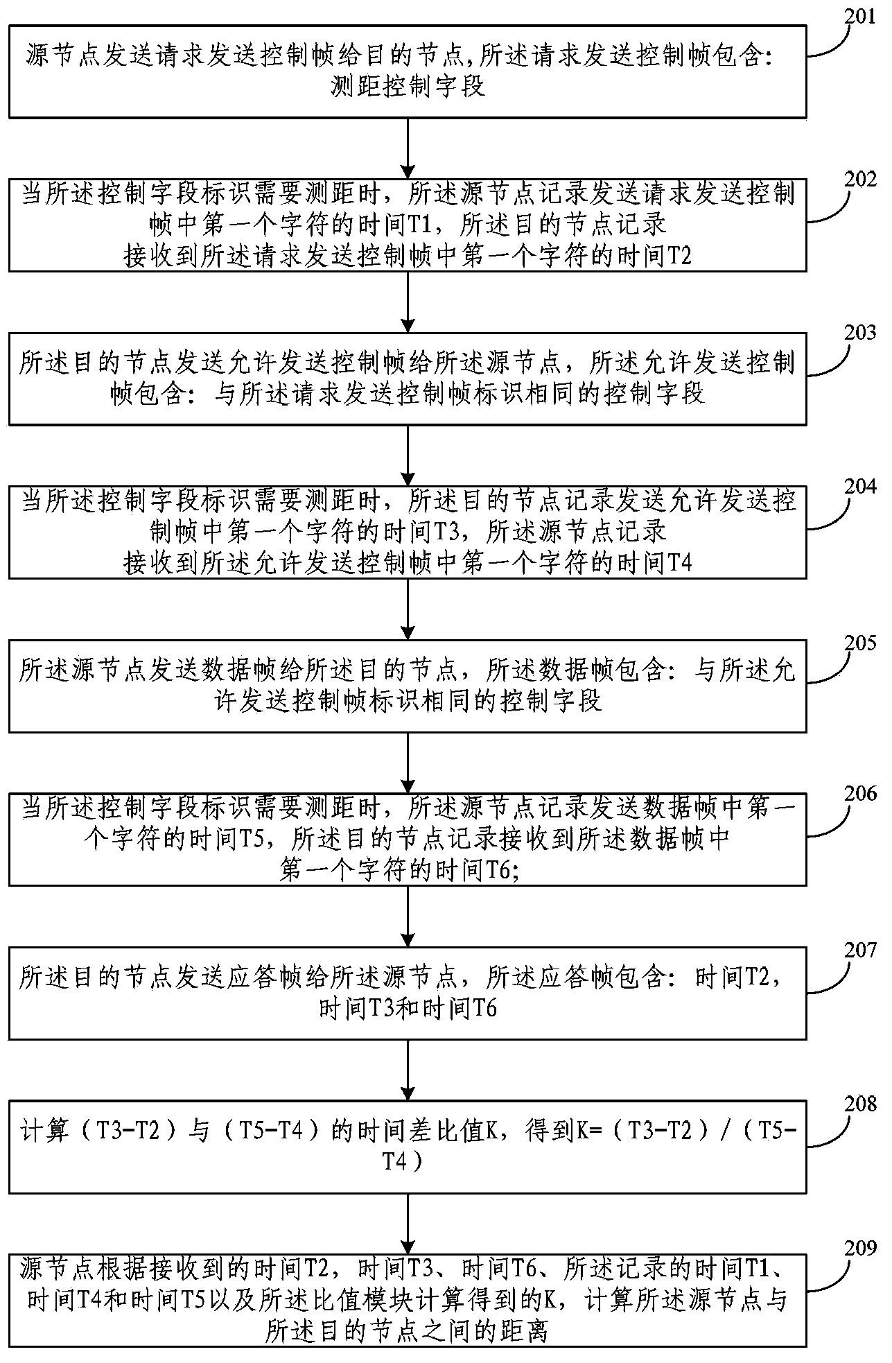
[0082]In the ranging method given in the first embodiment above, in practical applications, the lengths of the request to send control frame, the permission to send control frame, the data frame and the confirmation frame are different, causing the nodes to process various types of frames. The processing delay is different. Using the ranging method in Embodiment 1 will have the problems of large ranging error and low ranging accuracy. Therefore, the present invention also provides another ranging method, specifically as figure 2 As shown, it is a method flow chart of another ranging method disclosed in Embodiment 1 of the present application. The method includes the following steps:

[0083] Step 201: the source node sends a request to send control frame to the destination node, and the request to send control frame includes: a ranging control field, and the ranging control field is used to identify whether ranging is required;

[0084] Step 202: When the distance measuremen...

Embodiment 3

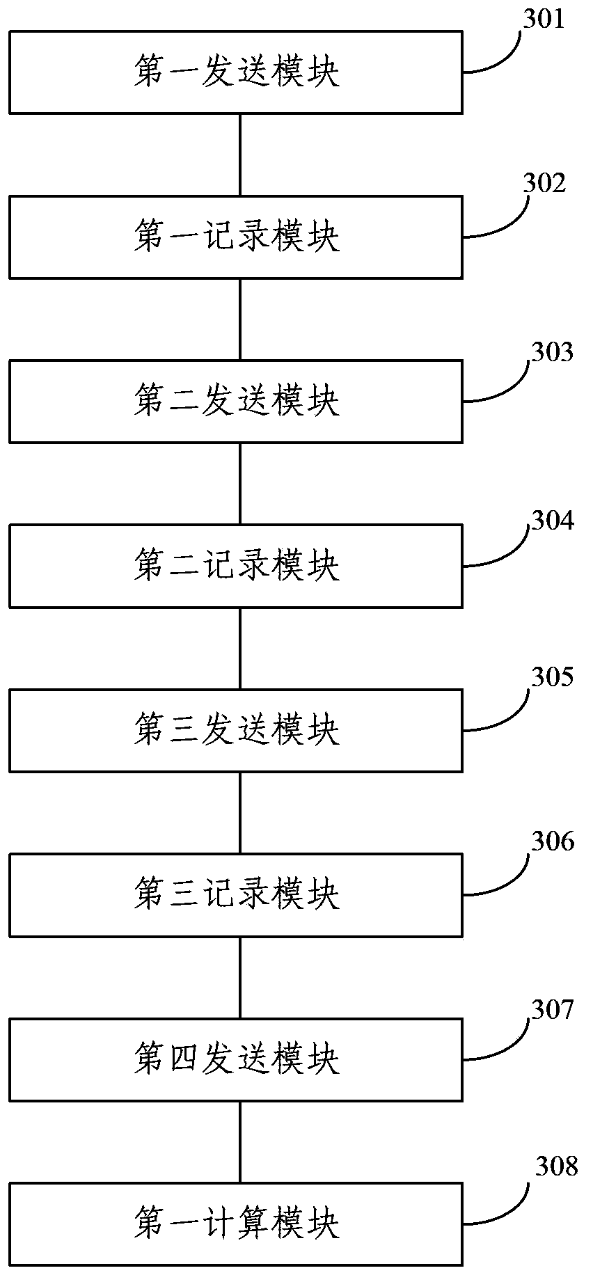
[0104] Corresponding to the distance measuring method in the first embodiment above, this embodiment of the present application provides a distance measuring device. see image 3 , which is a device structure diagram of a distance measuring device disclosed in Embodiment 3 of the present application. The device includes: a first sending module 301, a first recording module 302, a second sending module 303, a second recording module 304, a third A sending module 305 , a third recording module 306 , a fourth sending module 307 and a first calculating module 308 . The following will further introduce its internal structure and connection relationship in combination with the working principle of the device.

[0105] The first sending module 301 is used for the source node to send a request control frame to the destination node, where the request control frame includes: a ranging control field, and the ranging control field is used to identify whether ranging is required;

[0106...


PUM


Abstract

The embodiment of the invention discloses a ranging method and device. The ranging method comprises the steps that a source node sends a sending requesting control frame containing a control field used for indicating whether ranging is needed to determine whether the time when the source node sends a first character in the control frame or a data frame and the time when a destination node receives the first character in the control frame or the data frame need to be recorded; the distance between the source node and the destination node is calculated according to the recorded sending time and receiving time. In this way, ranging can be achieved while normal data communication of a communication network is achieved, data communication and ranging do not affect each other, and as a result, ranging expenses in the network are reduced, node energy consumption is reduced, and the life cycle of the network is prolonged.

Description

technical field [0001] The present invention relates to the communication field, in particular to a distance measuring method and device. Background technique [0002] In a wireless communication network, for most network applications, only knowing the sensory information of a node has no practical value. Only by knowing the location information of the node and obtaining the sensory information of the node can the information be of practical value, such as forest fire monitoring , medical and health care and other applications must know the node location information and the sensory information of the node, so that the application can play a practical application value. Therefore, node location is the position in the wireless communication network is particularly important. [0003] There are three commonly used positioning methods at present: the first is the global positioning system, but this system has high cost, high energy consumption, and is easily affected by the env...

Claims


Application Information

Patent Timeline
IPC IPC(8): H04W24/02H04W52/02
CPCG01S11/02H04W4/025H04W52/0209Y02D30/70
Inventor 张大龙张效义张瑞琴李青胡贇鹏
Owner THE PLA INFORMATION ENG UNIV
Learn More