Supercharge Your Innovation With Domain-Expert AI Agents!

Forming method of shaft parts with flanges

A technology of shaft parts and forming methods, which is applied in the direction of manufacturing tools, forging/pressing/hammer devices, forging/pressing/hammering machinery, etc., and can solve the problems of increasing equipment investment costs, large tonnage of forming equipment, and high equipment input costs , to achieve the effect of reducing input cost, reducing forming force and reducing extrusion area

Active Publication Date: 2016-04-27
HENAN UNIV OF SCI & TECH
View PDF3 Cites 0 Cited by
  • Summary
  • Abstract
  • Description
  • Claims
  • Application Information

AI Technical Summary

Problems solved by technology

When forming shaft parts with flanges, there are generally two methods used: first, extrusion molding, that is, to extrude a billet with a diameter equal to the flange diameter of the desired part on a press to extrude Forming the rod, in the extrusion process, the larger the extrusion area, the greater the extrusion force required. Therefore, when the flange diameter of the part is greatly different from the diameter of the rod, one-time extrusion molding is used, so The required extrusion force is relatively large, the tonnage of the forming equipment used is large, and the input cost of the equipment is high; second, upsetting forming, that is, upsetting the blank with a diameter equal to the diameter of the rod part of the required part on the press, The flange is formed by upsetting. Because the diameter of the flange is large, the upsetting force required is relatively large, which also requires a large-tonnage press, which increases the input cost of the equipment.

Method used


Image

  • Forming method of shaft parts with flanges
  • Forming method of shaft parts with flanges
  • Forming method of shaft parts with flanges

Examples


Embodiment Construction

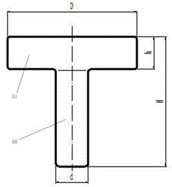
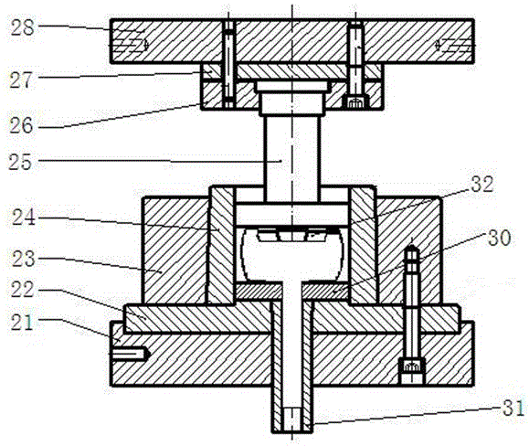
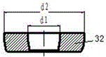
[0026] Examples of forming methods for shaft parts with flanges Figure 2~13 As shown: the following steps are included. The first step is to select a rod-shaped blank. The diameter of the rod-shaped blank is larger than the diameter of the shaft part of the shaft part and smaller than the diameter of the flange of the shaft part. The structure of the rod-shaped blank is as follows figure 2 As shown, D1 represents the diameter of the rod-shaped blank, and h0 represents the height of the rod-shaped blank; the second step is to extrude one end of the rod-shaped blank through the extrusion die, so that the rod-shaped blank is formed into the shaft part of the shaft , the structure of the extrusion die is as Figure 7 As shown: the extrusion die includes an extrusion upper die part and an extrusion lower die part, the extrusion upper die part includes an extrusion upper die base 8, and the lower end of the extrusion upper die base 8 is detachably connected with an extrusion upper...


PUM


Abstract

The invention relates to a forming method for a shaft component with a flange. The forming method comprises a first step of selecting a rod-shaped blank, wherein the diameter of the rod-shaped blank is larger than that of the rod section of the shaft component and is smaller than that of the flange of the shaft component; and a second step including the following forms: a first form comprising the steps of extruding one end of the rod-shaped blank through an extrusion mold so as to form the rod section of the shaft component from the rod-shaped blank, then upsetting the other end of the rod-shaped blank through an upsetting mold so as to form the flange of the shaft component from the rod-shaped blank; and a second form comprising the steps of upsetting one end of the rod-shaped blank through the upsetting mold so as to form the flange of the shaft component from the rod-shaped blank, and then extruding the other end of the rod-shaped blank through the extrusion mold so as to form the rod section of the shaft component from the rod-shaped blank. The forming method provided by the invention can reduce a forming force required during a forming process of the shaft component with the flange.

Description

technical field [0001] The invention relates to the technical field of metal extrusion molding, in particular to a molding method of shaft parts with flanges. Background technique [0002] Shaft parts with flanges such as figure 1 As shown: includes flange 51 and rod part 50 integrally arranged with the flange, in the figure D represents the diameter of the flange, h represents the height of the flange, d represents the diameter of the rod part, and H represents the height of the shaft parts. When forming shaft parts with flanges, there are generally two methods used: first, extrusion molding, that is, to extrude a billet with a diameter equal to the flange diameter of the desired part on a press to extrude Forming the rod, in the extrusion process, the larger the extrusion area, the greater the extrusion force required. Therefore, when the flange diameter of the part is greatly different from the diameter of the rod, one-time extrusion molding is used, so The required ext...

Claims


Application Information

Patent Timeline
Patent Type & Authority Patents(China)
IPC IPC(8): B21C23/02B21J5/08B21J13/02
Inventor 宋克兴周延军赵培峰张学宾郜建新张彦敏国秀花刘亚民李宁宁乔艳艳何霞张素霞赵亚永
Owner HENAN UNIV OF SCI & TECH
Features
  • R&D
  • Intellectual Property
  • Life Sciences
  • Materials
  • Tech Scout
  • Unparalleled Data Quality
  • Higher Quality Content
  • 60% Fewer Hallucinations
Learn More