
Device with axially clamped plunger for amplifying the input force

A technology of input force and equipment, applied in the direction of transportation and packaging, vehicle parts, brakes, etc., can solve the problems of complexity, high manufacturing cost and high weight, and achieve the effect of improving air guidance, reducing component prices and reducing forming force

Active Publication Date: 2022-06-28
CONTINENTAL AUTOMOTIVE TECH GMBH
View PDF7 Cites 0 Cited by
  • Summary
  • Abstract
  • Description
  • Claims
  • Application Information

AI Technical Summary

Problems solved by technology

The accompanying manufacturing tooling was seen as complex and prohibitively expensive and heavy to manufacture

Method used


Image

  • Device with axially clamped plunger for amplifying the input force
  • Device with axially clamped plunger for amplifying the input force
  • Device with axially clamped plunger for amplifying the input force

Examples


Embodiment Construction

[0019] figure 1 and figure 2

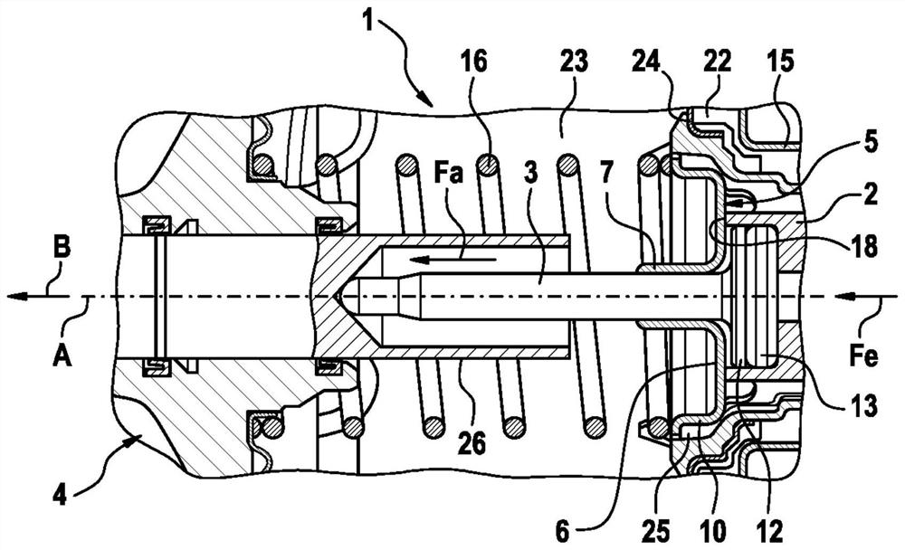
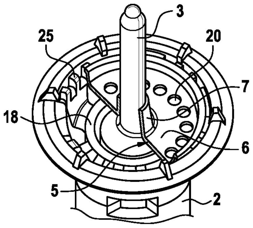
[0020] In such a device 1 , which is designed as a pneumatic brake booster, the input force Fe generated by the driver is introduced and amplified by means of a vacuum chamber 23 arranged in the housing 15 and a ventilated air-exhaust system. The pressure difference between the working chambers 22 acts on the movable working wall 24 with a large surface which can seal the separation of the two chambers and through the module 2 coupled thereon and clamped on the module 2 with a structure configured to The pressure rod 3 between the pistons 26 of the force receiving device 4 of the master cylinder is output to the piston 26 as an amplified output force Fa.

[0021] The pressure lever 3 is of rotationally symmetrical design with respect to the actuating axis A and, in addition to the elongated pin-shaped cylindrical body, has a radially expanded flat base 12 on the module side, by means of which the pressure lever is axially It rests on an elast...


PUM


Abstract

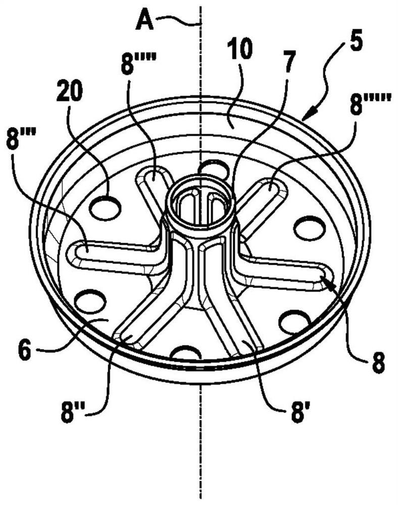
The invention relates to a device (1) for amplifying an input force (Fe), said device having a compression rod (3) and a support element (5) for radially supporting the compression rod (3), wherein the support The element (5) has a hollow guide shank (7) protruding forward from the base (6) in the steering direction (B), through which the pressure rod (3) is guided and radially supported on the guide shank (7). handle. In order to provide an improved device (1) of this type which achieves a sufficient tipping resistance of the clamped pressure rod (3) with the least possible engagement into the device construction and with reduced weight and manufacturing costs According to the invention it is proposed that the support element (5) has at least one profile (8) for increasing the overturning rigidity of the guide handle (7) with respect to the actuation axis (A), said at least one profile passing at least partially through the bottom ( 6) and guide handle (7) extend.

Description

technical field [0001] The invention relates to a device for amplifying an input force with an axially clamped pressure rod for transmitting the amplified output force to a force receiving device. Background technique [0002] Such a device can have various embodiments and is known, for example from DE 10 2015 209 785 A1, as a pneumatic brake booster for a hydraulic motor vehicle brake system, which is related to a force Combined with the master brake cylinder of the receiving device. [0003] This device is characterized by a pressure rod that is axially clamped between the piston of the master brake cylinder and the module movable in the brake booster. The movable modules usually contain actuating components and control valves for manual and / or automatic external actuation, are surrounded by radial gaps due to their design and are guided and sealed by radial sealing elements, so that they are forced to with small radial clearance. In relation to the elasticity of the ho...

Claims


Application Information

Patent Timeline
Patent Type & Authority Patents(China)
IPC IPC(8): B60T13/567
CPCB60T13/567B60T13/57
Inventor J·法勒S·迈因茨
Owner CONTINENTAL AUTOMOTIVE TECH GMBH
Learn More