
Method of de-interleaving interleaved data samples sequences, and associated system

a data sample and sequence technology, applied in the field of de-interleaving sequences of interleaved data samples, can solve the problems of reducing the necessary memory size and memory access rate, affecting and achieve the effect of great impacting the overall die area and power consumption

Active Publication Date: 2009-03-17
STMICROELECTRONICS INT NV
View PDF7 Cites 2 Cited by
  • Summary
  • Abstract
  • Description
  • Claims
  • Application Information

AI Technical Summary

Benefits of technology

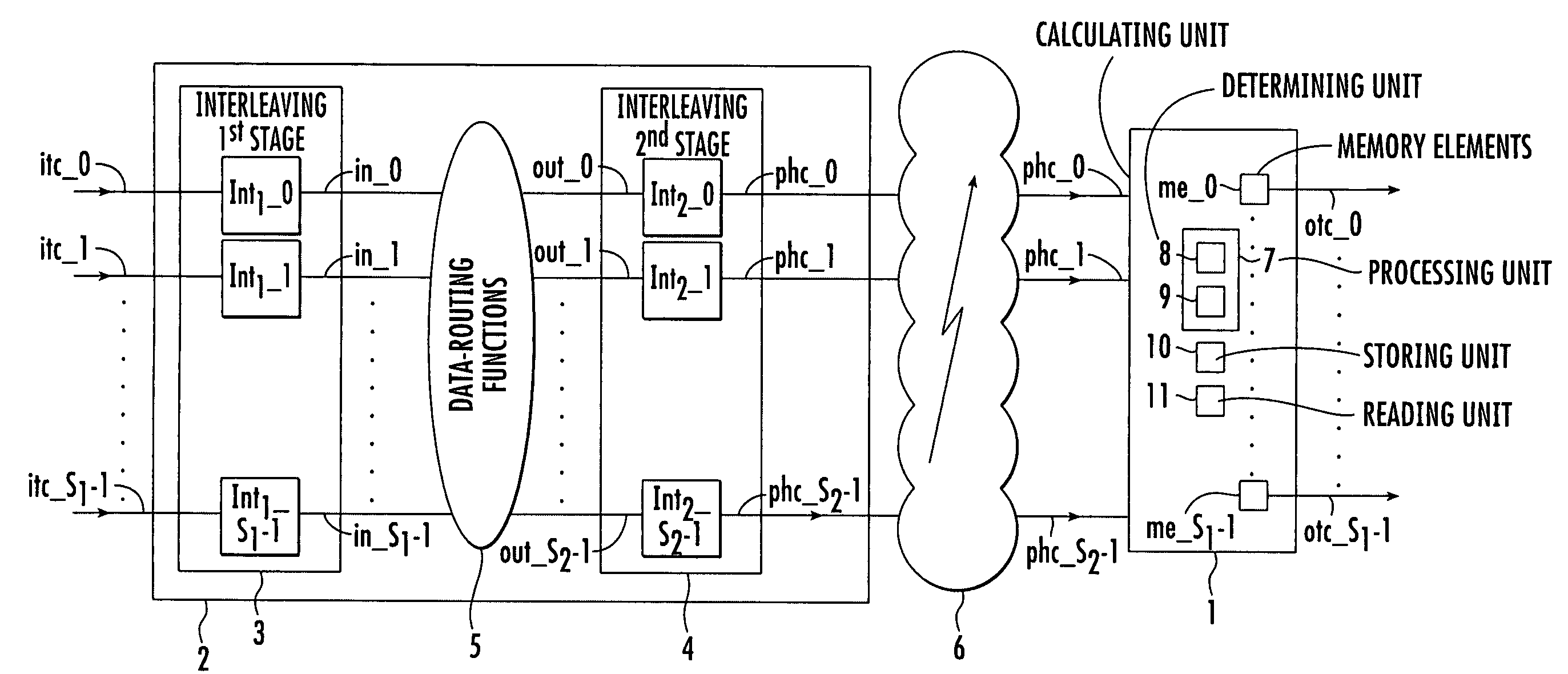
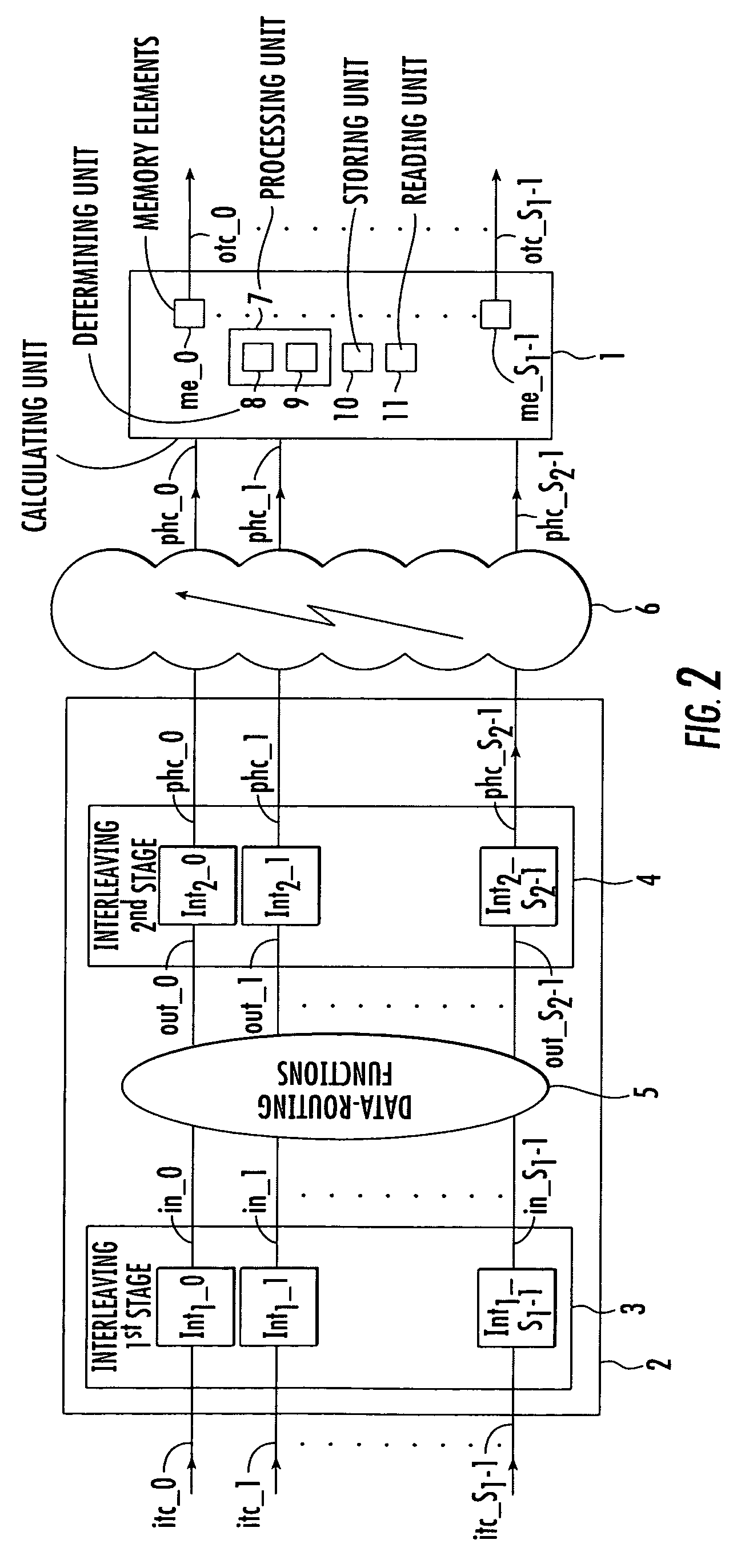
[0004]An object of the invention is to de-interleave data samples interleaved by a two-stage multi-interleaving device, without using a traditional de-interleaving method, in order to reduce a de-interleaving multi-stage problem into a one-stage problem. This significantly reduces the necessary memory size and memory access rate, which in turn, greatly impacts the overall die area and power consumption.
[0005]This and other objects, advantages and features in accordance with the invention is provided by an efficient transformation of a two-stage block interleaving subsystem comprising respectively S1 and S2 interleavers per stage. The processing may include writing data samples row by row, performing inter-columns permutations, and reading out data samples column by column. The interleavers may be connected through inter-stage data-routing functions into a one-stage representation requiring fewer resources and data routing to provide an area-efficient, low power approach.

Problems solved by technology

This significantly reduces the necessary memory size and memory access rate, which in turn, greatly impacts the overall die area and power consumption.

Method used


Image

  • Method of de-interleaving interleaved data samples sequences, and associated system
  • Method of de-interleaving interleaved data samples sequences, and associated system
  • Method of de-interleaving interleaved data samples sequences, and associated system

Examples


Embodiment Construction

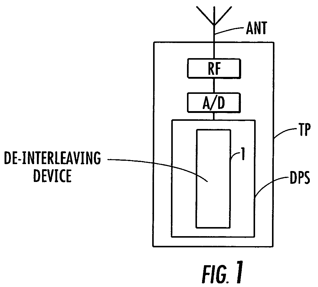
[0035]Referring now FIG. 1, a de-interleaving system according to the invention is illustrated, which is incorporated in the reception chain of a cellular mobile phone TP. However, the invention is not limited to this particular application.

[0036]The interleaved signal is received by the antenna ANT and processed by the radio frequency stage RF of the receiver. At the output of the RF stage, the signal is converted into the digital domain by an A / D converter. The converted signal is transmitted to a digital process stage DPS which comprises a system 1 of de-interleaving according to the invention, and processes the digital baseband signal.

[0037]Referring now to FIG. 2, a two-stage multi-interleaving device 2 is represented. This term means a device with two stages, each stage having a plurality of interleavers. The two-stage multi-interleaving device 2 comprises a first interleaving stage 3, a second interleaving stage 4, and an inter-stage of predetermined data-routing functions 5 ...


PUM


Abstract

A method for de-interleaving S2 received sequences of interleaved received data samples respectively issued from S2 physical channels and to be associated with S1 output transport channels is provided. The S2 received sequences have been delivered, before transmission by a two-stage multi-interleaving device, from S1 initial sequences of ordered data samples respectively associated to S1 initial transport channels. The two-stage multi-interleaving device includes a first stage including S1 interleaving blocks respectively associated to the S1 initial transport channels, a second stage including S2 interleaving blocks respectively associated to the S2 physical channels, and an inter-stage of predetermined data-routing functions connected between the first and second stages.

Description

FIELD OF THE INVENTION[0001]The invention relates in general to de-interleaving sequences of interleaved data samples. An application of the invention is directed in general to wireless communication systems, and more particularly, to CDMA systems such as the different CDMA based mobile radio systems including the 3GPP systems operating in accordance with the well-known 3GPP standard.BACKGROUND OF THE INVENTION[0002]An interleaving device is, in particular, located between a channel encoder and a modulator within a transmitter. In the same way, a de-interleaving device is located between a demodulator and a channel decoder within a receiver.[0003]Interleaving scrambles the processing order to break up neighbor relations in successive data samples, and de-interleaving brings them into the original sequences again. Current de-interleaving approaches present several problems, notably a high memory access rate, a memory re-use bottleneck, and no scalability.SUMMARY OF THE INVENTION[0004...

Claims


Application Information

Patent Timeline
Patent Type & Authority Patents(United States)
IPC IPC(8): G06F11/00G11C29/00H03M13/27
CPCH03M13/2703H03M13/2792H03M13/2796H03M13/6505
Inventor WELLIG, ARMINZORY, JULIEN
Owner STMICROELECTRONICS INT NV
Learn More