
Magnet brake used for lifting equipment

A technology of electromagnetic brakes and brakes, applied in the direction of hoisting devices, etc., can solve the problems of poor braking effect, poor comfort, incomplete separation of brake pads and brake discs, etc., and achieve good braking effect.

Active Publication Date: 2015-01-21
BEIJING SWORD ELECTRIC IND
View PDF8 Cites 2 Cited by
  • Summary
  • Abstract
  • Description
  • Claims
  • Application Information

AI Technical Summary

Problems solved by technology

[0003] The traditional electromagnetic brake for the elevator traction machine is directly installed on the machine base. Due to the long braking force arm, the brake shaft is prone to twist during the braking process, resulting in incomplete separation of the brake pad and the brake disc when the electromagnetic brake is energized. , poor braking effect, loud noise, poor comfort

Method used


Image

  • Magnet brake used for lifting equipment
  • Magnet brake used for lifting equipment
  • Magnet brake used for lifting equipment

Examples


Embodiment Construction

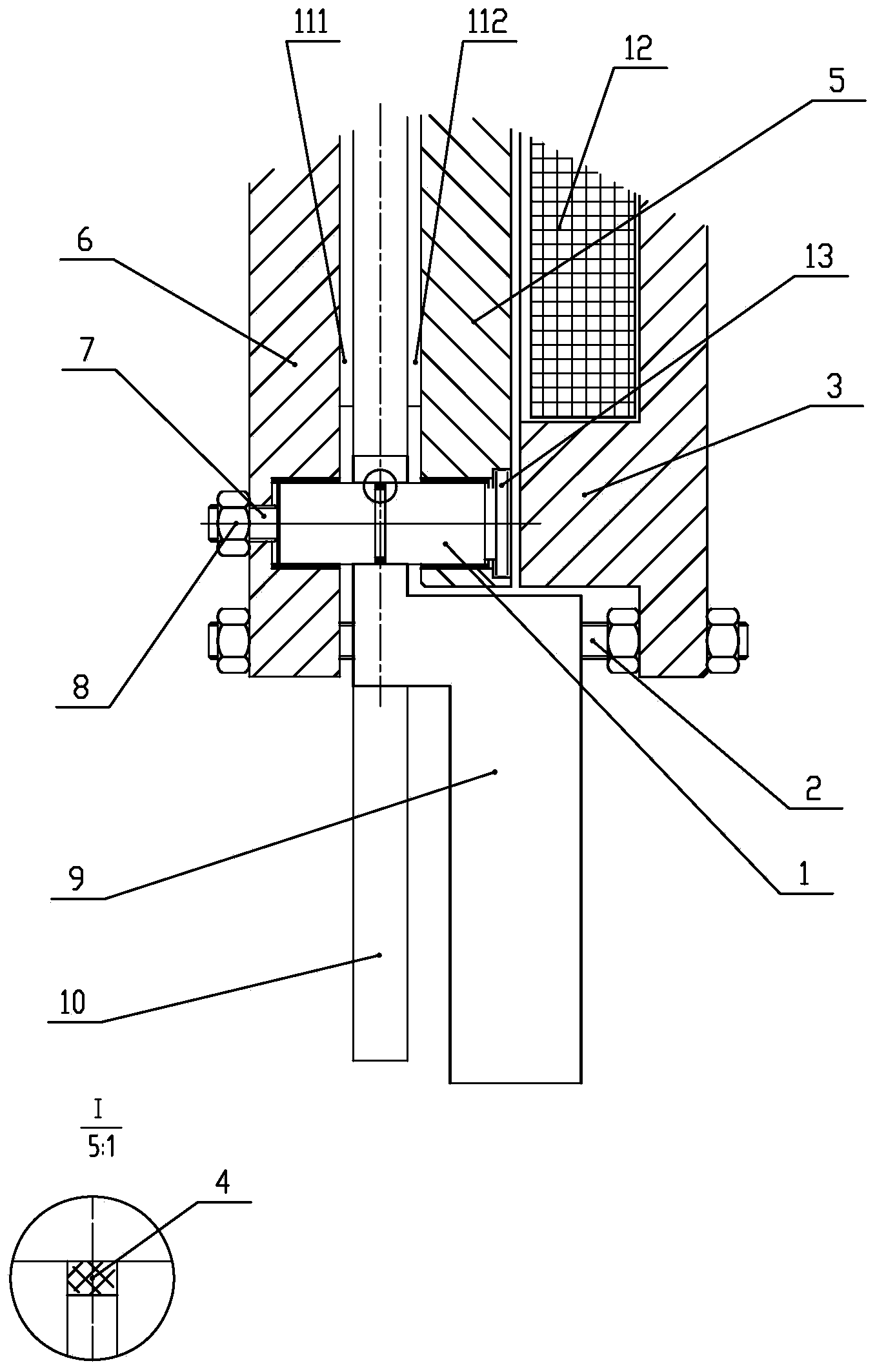
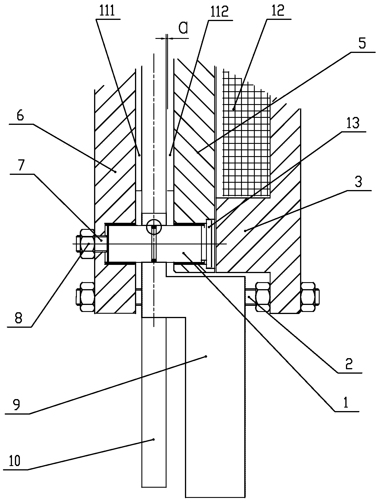
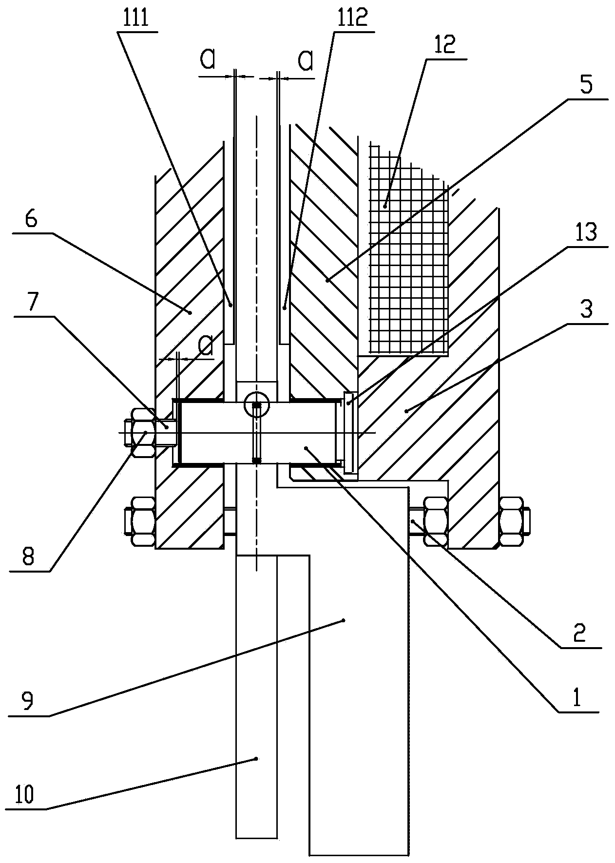
[0014] Such as Figure 1-3 As shown, this electromagnetic brake for lifting equipment includes a brake seat 3, an armature 5, a shoe 6, an electromagnet 12, a brake disc 10, and a brake pad 11. The electromagnet is installed on the brake seat, and the shoe The armature is arranged on the left and right sides of the brake disc. The brake pads include first and second brake pads 111 and 112. The right side of the shoe is provided with a first brake pad 111, and the left side of the armature is provided with a second brake pad 112. And the right side of the armature is adjacent to the electromagnet, the brake disc is installed on the hoisting machine of the hoisting equipment, a pin 1 is provided on the support plate 9 of the hoisting machine, and the left and right parts of the pin are slidably connected to the shoe and the armature. , The right end of the pin is provided with a flange 13, which is in the groove on the right side of the armature. The middle of the pin is covered ...


PUM

PropertyMeasurementUnit
Slope angleaaaaaaaaaa

Abstract

The application discloses a magnet brake used for lifting equipment. The magnet brake has the advantages that brake blocks and a brake disc are separated completely when in power-on and pull-in, the brake effect is good, the noise is low, the comfort feeling is good, the reliability is high and the service life is prolonged. The magnet brake comprises a brake seat, an armature, a horseshoe, an electromagnet, the brake disc and the brake blocks; the electromagnet is mounted on the brake seat; the horseshoe and the armature are arranged on the left and right sides of the brake disc respectively; the brake blocks include a first brake block and a second brake block; the first brake block is arranged on the right side of the horseshoe; the second brake block is arranged on the left side of the armature, and the right side of the armature is close to the electromagnet; the brake disc is mounted on a tractor of the lifting equipment; a pin is mounted on a support plate of the tractor; the left part and the right part of the pin are connected with the horseshoe and the armature in a sliding manner respectively; a flange is arranged at the right end of the pin and positioned in a groove in the right side of the armature; a rubber ring sleeves the middle part of the pin; the radial center of the rubber ring and that of the brake disc are in the same line; the brake seat, the support plate and the horseshoe are fixedly connected.

Description

Technical field [0001] The invention belongs to the technical field of electromagnetic brakes, and specifically relates to an electromagnetic brake used for lifting and hoisting equipment, which mainly includes elevator traction machines, cranes and the like. Background technique [0002] With the rapid development of the elevator industry, my country's elevator market has higher and higher requirements for elevator technology and product quality. The performance of elevators depends largely on the performance of elevator traction machines. Electromagnetic brake is one of the most important safety components of elevator equipment. Its performance and working status are directly related to the safety of elevator equipment and elevator users. The working process is: when the traction machine hauls the car to the stair stop, the elevator traction machine requires braking performance at this time, and the brake set on the traction machine locks the brake pads and the brake disc after...

Claims


Application Information

Patent Timeline
IPC IPC(8): B66D5/14B66D5/30
CPCB66D5/14B66D5/30
Inventor 刘宏鑫王宝胜赵文彬
Owner BEIJING SWORD ELECTRIC IND
Learn More