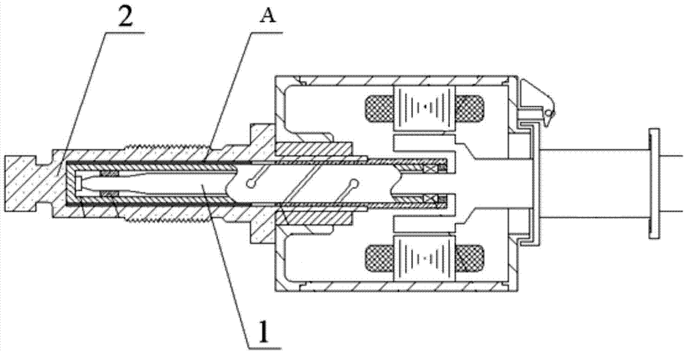
Spinning frame motor type spindle vibration reducing method based on magnetic damping
An electromechanical and magnetic damping technology, applied in textiles and papermaking, can solve problems such as high precision requirements, high manufacturing costs, and complicated manufacturing processes, and achieve the effect of reducing manufacturing costs and reducing use costs
- Summary
- Abstract
- Description
- Claims
- Application Information
AI Technical Summary
Problems solved by technology
Method used
Image
Examples
Embodiment 1
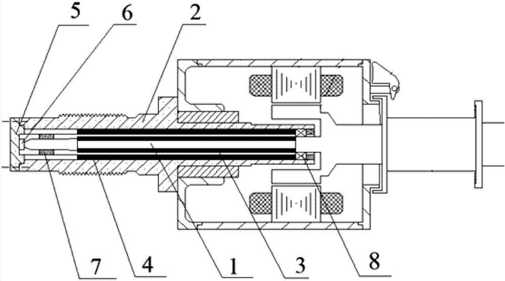
[0017] Embodiment 1: the method for reducing the vibration of the spinning frame motor type spindle based on the homosexual repulsion of magnetic materials, figure 2 It is the engineering diagram corresponding to this embodiment.
[0018] Among them, the stator part is to press the motor stator core containing the coil into the motor casing, and then cooperate them with the spindle foot 2 . For the rotor part, a needle bearing 8 is installed on the top of the spindle foot 2, a thrust bearing 6 is installed at the bottom of the spindle, and the tip of the spindle rod 1 is placed on the thrust bearing 6. The bottom of the ingot and the bottom end cover 5 are in one structure, and are connected with the ingot foot by screws. A sliding bearing 7 is provided between the tip of the spindle rod 1 and the spindle foot 2 for radial support. The motor rotor is placed inside the stator core, and the rotor core embedded with magnetic steel is aligned with the stator part; the outer mid...
Embodiment 2
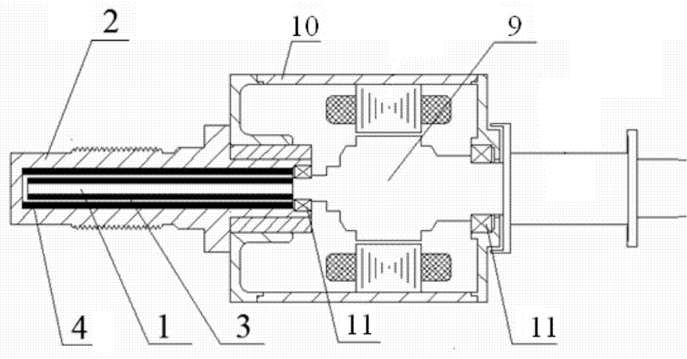
[0019] Embodiment 2: the method for reducing the vibration of the spinning frame motor type spindle based on the homosexual repulsion of magnetic materials, image 3 It is the engineering diagram corresponding to this embodiment.
[0020] Wherein, for the stator part, the motor stator core containing the coils is pressed into the motor housing 10, and then they are matched with the spindle foot 2. The rotor part 9 is axially positioned by rolling bearings 11 arranged on the upper part of the spindle foot 2 and the motor housing 10 . The motor rotor is placed inside the stator core, and the rotor core embedded with magnetic steel is aligned with the stator; the lower surface of the spindle bar 1 is embedded with magnetic steel 3, and inserted into the spindle foot 2, and the corresponding position inside the spindle foot 2 is installed with a The magnetic ring 4 of the same polarity of the magnetic steel 3, its section is shown in Figure 4 . The shaft extension of the rotor...
PUM
 Abstract
Description
Claims
Application Information
 - R&D
- Intellectual Property
- Life Sciences
- Materials
- Tech Scout
- Unparalleled Data Quality
- Higher Quality Content
- 60% Fewer Hallucinations
Browse by: Latest US Patents, China's latest patents, Technical Efficacy Thesaurus, Application Domain, Technology Topic, Popular Technical Reports.
© 2025 PatSnap. All rights reserved.Legal|Privacy policy|Modern Slavery Act Transparency Statement|Sitemap|About US| Contact US: help@patsnap.com


