
Centering kits for component supports

A component and component technology, applied in the field of centering components, can solve the problems of reduced downtime, high investment costs, etc., and achieve the effect of avoiding skew

Active Publication Date: 2019-02-22
布勒特耶自动控制设备有限责任公司
View PDF6 Cites 0 Cited by
  • Summary
  • Abstract
  • Description
  • Claims
  • Application Information

AI Technical Summary

Problems solved by technology

The resulting long downtimes of the usually very expensive processing stations correspondingly significantly reduce their availability and thus lead to significantly higher investment costs per flying body produced

Method used


Image

  • Centering kits for component supports
  • Centering kits for component supports
  • Centering kits for component supports

Examples


Embodiment Construction

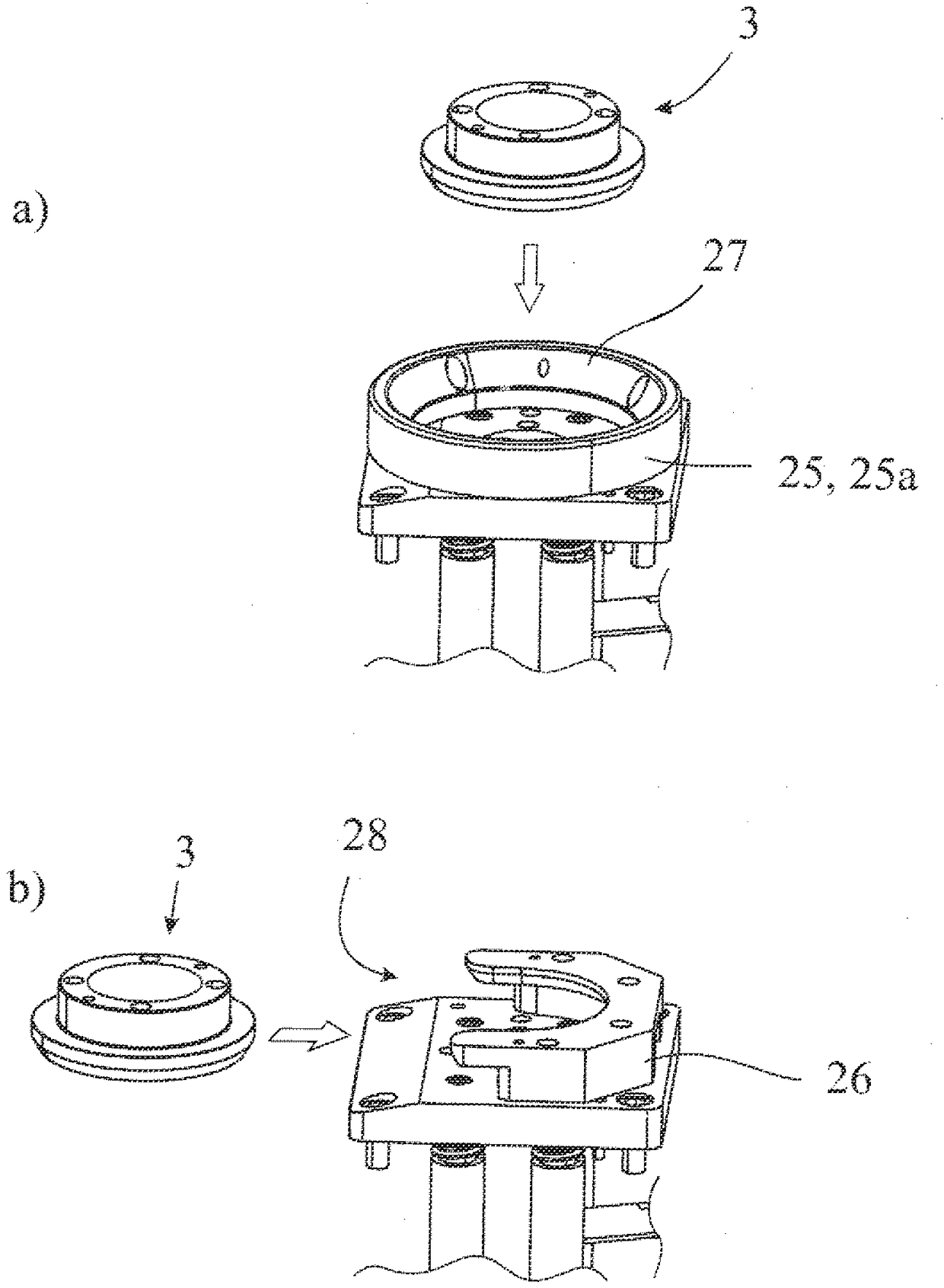
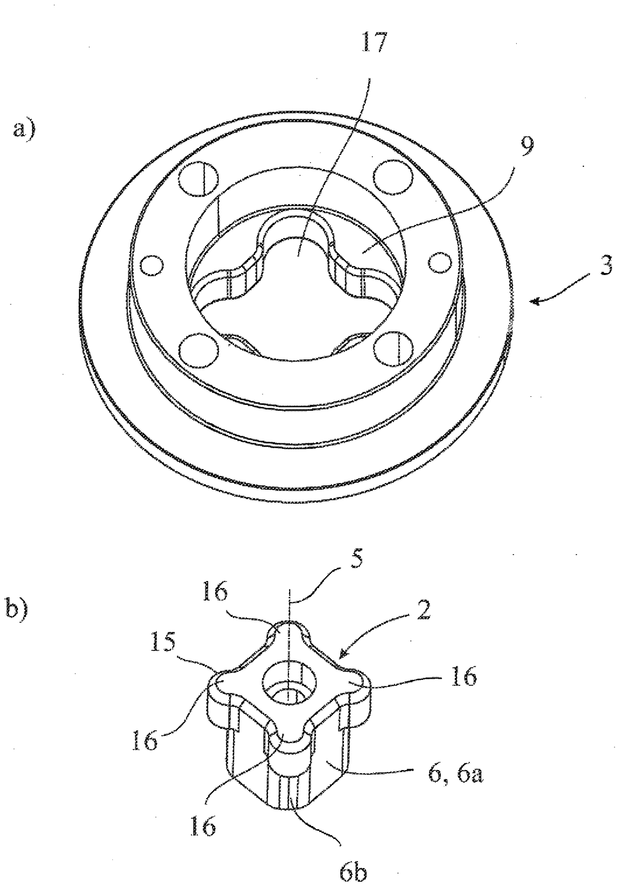
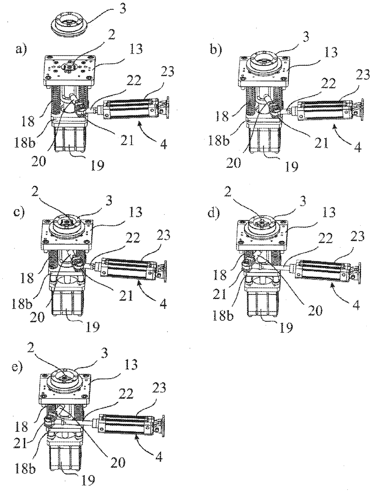
[0027] exist figure 1 A component carrier 1 for an aircraft structural component, in particular a clamping frame 1a, is shown with four proposed centering assemblies. additionally, figure 1 An enlarged oblique view of one of these proposed centering arrangements in the component carrier 1 is also reflected.

[0028] The shown clamping frame 1 a is used in particular in a machining station (not shown here) for aircraft structural components. In particular, the fuselage and wings of the aircraft and their components are among the structural components of the aircraft that can be accommodated by the clamping frame 1a.

[0029] The proposed centering assembly comprises a centering pin 2 and a centering receptacle 3 for the centering pin 2, which are respectively located at figure 2 Shown enlarged in b and 2a.

[0030] The centering receptacle 3 is thus set up to accommodate the centering pin 2 in its opening. In this case, the centering receptacle 3 is arranged on the workpi...


PUM


Abstract

The invention relates to a centering assembly for component supports (1), in particular for clamping frames (1a) for aircraft structural components, with centering pins (2), for centering pins (2 ) and a rotary drive (4) for rotating the centering pin (2) around the longitudinal axis (5) of the centering pin (2), so that the centering pin (2) can be rotated by is brought into centering engagement with the centering receptacle (3). Furthermore, the invention relates to a method for centering and locking a centering receptacle (3).

Description

technical field [0001] The invention relates to a centering set (Zentrieranordnung) according to the invention for a component carrier (Bauteiltraeger) and a centering receptacle (Zentrieraufnahme) according to the invention for centering and locking with a centering pin (Zentrierbolzen) )Methods. Background technique [0002] Aircraft and other flying objects often have very large structural elements, such as wings, fuselages or parts thereof. During the automated production of flying bodies, these structural components are handled in correspondingly large processing stations and processed by different machine tools. The exemplary work step setting automatically sets up a series of riveted joints, which in the past often had to be carried out manually. [0003] From the prior art and in particular from the most recent document US 8,220,134, a machining station for aircraft structural components is known, in which a rectangular clamping frame (Aufspannrahmen) is used as a ...

Claims


Application Information

Patent Timeline
Patent Type & Authority Patents(China)
IPC IPC(8): B23Q3/00
CPCB23Q3/18B23Q3/183Y10T29/49998Y10T29/53983Y10T29/5177Y10T29/53091Y10T29/53687Y10T29/53961Y10T29/53978B64F5/10B25B11/00B23Q1/015B23Q1/25
Inventor C.奥伊斯特维曼
Owner 布勒特耶自动控制设备有限责任公司
Learn More