
Internal limiting anti-rotation structure of driving brake caliper assembly

A technology of anti-rotation structure and limit structure, which is applied in the direction of brake actuators, brake parts, and axially joined brake parts, etc., which can solve problems such as prone to tilting, affecting stability, and poor assembly process. To achieve the effect of improving the relative axial tilt, improving the convenience of assembly, and ensuring the axial movement

Pending Publication Date: 2021-11-16
WUHU BETHEL AUTOMOTIVE SAFETY SYST
View PDF1 Cites 0 Cited by
  • Summary
  • Abstract
  • Description
  • Claims
  • Application Information

AI Technical Summary

Problems solved by technology

When the moving parts and anti-rotation parts in the brake caliper assembly are placed in a free state, the centering in the axial direction cannot be achieved through the side-to-side limit structure, which is prone to tilt and poor assembly process; the side-to-side structure The weight increase of components caused by the universal design of electric drive or electric and hydraulic drive brake calipers of different cylinder diameter series is more obvious
[0003] Patent No. CN107489714A discloses an electric caliper brake. By setting a filling part with a rotation preventing surface on the outside of the nut part and setting a rotation preventing platform in the piston, the nut part is aligned by the cooperation between the rotation preventing surface and the rotation preventing platform. To limit the rotation and convert the rotational motion of the main shaft into linear motion, but by filling the piston with filling parts to limit and prevent rotation, a large amount of material needs to be consumed, resulting in increased production costs; Patent No. CN111412231A discloses an electronic The anti-rotation structure of the parking caliper piston, by setting the step part and the limit part inside the piston, can limit and prevent the bolt from rotating. The centering in the axial direction is achieved through the side-to-side limit structure. The screw sleeve is easy to tilt in the piston, and the assembly process is poor, which affects the stability of use. Therefore, it is very important to solve this problem.

Method used


Image

  • Internal limiting anti-rotation structure of driving brake caliper assembly
  • Internal limiting anti-rotation structure of driving brake caliper assembly
  • Internal limiting anti-rotation structure of driving brake caliper assembly

Examples


Embodiment 1

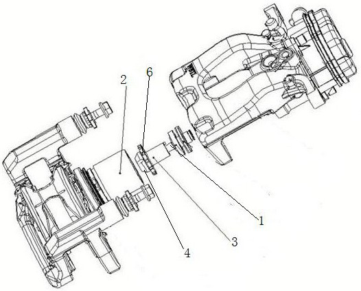
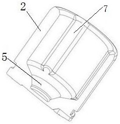
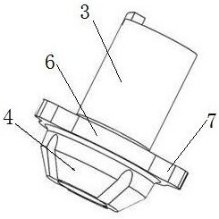
[0021] Such as Figure 4 As shown, the concave-convex limiting structure 7 adopts a groove and a boss structure, the groove is arranged on the inner side of the piston 2, the boss is arranged on the outer side of the limit block 6, the boss is snapped into the inner side of the groove, and is in contact with the surface of the groove Limiting and anti-rotation are performed, and the grooves and bosses are equidistantly distributed to ensure the supporting effect of the piston 2 on the brake screw sleeve 3, so that the brake screw sleeve 3 is kept axially placed.

Embodiment 2

[0023] Such as Figure 5 As shown, the concave-convex limiting structure 7 adopts a boss and a groove structure, the boss is arranged on the inner side of the piston 2, the groove is arranged on the outer side of the limit block 6, and the groove and the surface of the boss are in contact with each other to limit and prevent rotation. Both the bosses and the grooves are equidistantly arranged to ensure the supporting effect of the piston 2 on the brake screw sleeve 3 and keep the brake screw sleeve 3 placed axially.

Embodiment 3

[0025] Such as Figure 6 As shown, the concave-convex limiting structure 7 adopts a boss and a boss structure, and the bosses are respectively arranged on the inner side of the piston 2 and the outer side of the limiting block 6, and the boss in the piston 2 is in contact with the side of the boss on the outer side of the limiting block. Cooperate, the bosses are all non-equidistantly distributed, one or more bosses on the limit block 6 are located on the adjacent side of the inner boss of the piston, so that the bosses and bosses are in contact with each other to achieve forward and reverse directions of rotation. limit function.

[0026] The groove corresponding to the piston and the end area of ​​the boss contain structural features such as chamfers or rounded corners to realize the guiding function of assembly.

[0027] The groove and the boss can choose circular arc structure and U-shaped groove structure.


PUM


Abstract

The invention provides an internal limiting anti-rotation structure of a driving brake caliper assembly. The structure comprises a brake screw rod and a piston, the left end of the brake screw rod is provided with a brake threaded sleeve in a sleeved manner, the brake threaded sleeve extends into the piston, the lower end of the brake threaded sleeve is connected with a conical block, a conical groove is correspondingly formed in the piston, a limiting block is arranged on the brake threaded sleeve, the limiting block and the piston are internally and correspondingly provided with three concave-convex limiting structures for limiting, and the three concave-convex limiting structures are distributed in a triangular structure manner. Anti-rotation limiting is conducted on the brake threaded sleeve through the concave-convex limiting structures, the concave-convex limiting structures are distributed through the triangular structure, the brake threaded sleeve can move longitudinally in the piston more stably, and the limiting and anti-rotation effect is improved.

Description

technical field [0001] The invention relates to the technical field of brake caliper assembly equipment, in particular to an internal position limiting and anti-rotation structure of a driving brake caliper assembly. Background technique [0002] When the electric drive or electro-hydraulic combination drive brake caliper assembly is used in the process of driving brake or parking brake, the screw drive, ball screw pair and other structures are used to generate the clamping force, and the screw drive counterpart (such as Parking brake nut, ball screw nut) is limited and anti-rotated so that it overcomes the rotational resistance to prevent follow-up rotation to achieve axial movement and generate clamping force. The anti-rotation of this type of structure is mostly realized by means of two-sided side-to-side limit methods arranged symmetrically in axially moving parts (such as pistons). When the moving parts and anti-rotation parts in the brake caliper assembly are placed i...

Claims


Application Information

Patent Timeline
IPC IPC(8): F16D65/00F16D65/16F16D121/04
CPCF16D65/005F16D65/16F16D2121/04
Inventor 李尚阳丁文艳李运动
Owner WUHU BETHEL AUTOMOTIVE SAFETY SYST
Learn More