Vehicle lamp

A technology for lamps and vehicles, applied in the direction of headlights, road vehicles, vehicle parts, etc., to achieve the effect of improving conspicuousness

Active Publication Date: 2015-01-21
KOITO MFG CO LTD
View PDF4 Cites 13 Cited by
  • Summary
  • Abstract
  • Description
  • Claims
  • Application Information

AI Technical Summary

Problems solved by technology

There is room for improvement in the conspicu

Method used


Image

  • Vehicle lamp
  • Vehicle lamp
  • Vehicle lamp

Examples


no. 1 example

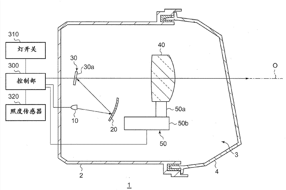
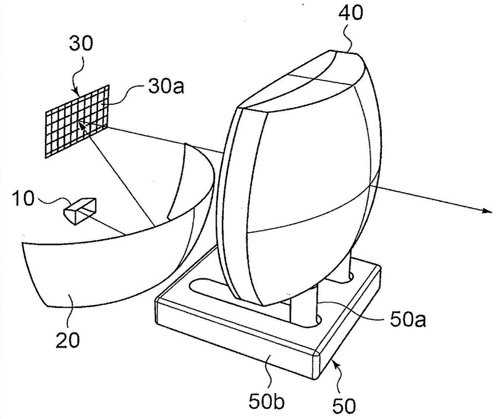
[0020] figure 1 is a vertical sectional view showing a schematic structure of the vehicle lamp according to the first embodiment. Figure 2A is a perspective view schematically showing the internal structure of the vehicle lamp according to the first embodiment. The vehicular lamp 1 according to the present embodiment is a vehicular headlamp device having a pair of headlamp units arranged left and right in front of the vehicle. The pair of headlamp units are formed in substantially the same configuration except that the configurations of the headlamp units are mirror images of each other, and therefore figure 1 The structure of one of the headlamp units is shown as a vehicle lamp 1 .

[0021] The vehicle lamp 1 includes a lamp body 2 having an opening on the front side of the vehicle, and a cover 4 arranged in front of the lamp body 2 and attached to cover the opening of the lamp body 2 . The cover 4 is formed of translucent resin or glass. In the lamp chamber 3 defined by...

no. 2 example

[0048] The structure of the vehicular lamp according to the second embodiment is basically the same as that of the vehicular lamp 1 according to the first embodiment except that the light image forming portion is a liquid crystal shutter. The same components as those of the first embodiment are assigned the same reference numerals and description and illustration thereof will be appropriately omitted. Image 6 is a perspective view schematically showing the internal structure of the vehicular lamp according to the second embodiment. exist Image 6 In , the illustration of the optical component shifting unit 50 is omitted.

[0049] In the vehicular lamp 1 according to the present embodiment, the optical image forming section 30 is constituted by a liquid crystal shutter, and is arranged on a path of light source light between the light source 10 and the optical member 40 . Therefore, light from the light source enters the light image forming portion 30 from the rear of the la...

no. 3 example

[0052] The structure of the vehicular lighting fixture according to the third embodiment is basically the same as that of the vehicular lighting fixture 1 according to the first or second embodiment except that the optical part is constituted by two lenses. Components that are the same as those of the first or second embodiment are assigned the same reference numerals and descriptions and illustrations thereof will be appropriately omitted. Figure 7A is a perspective view schematically showing the internal structure of the vehicular lamp according to the third embodiment when the optical member is in the first state. Figure 7B is a vertical sectional view schematically showing the internal structure of the vehicular lamp according to the third embodiment when the optical member is in the first state. Figure 7C is a perspective view schematically showing the internal structure of the vehicular lamp according to the third embodiment when the optical member is in the second st...


PUM


Abstract

A vehicle lamp includes a light image generation section (30) which produces a light image, an optical element (40) that projects the light image, and a section (50) for displacing the optical element, the switching an arrangement state of the optical element (40) between a first state in which a distance between a focal point of the optical element (40) and a photo-emitting surface of the light image forming portion (30) is a predetermined distance, and a second state in which the distance is greater than the predetermined distance in the first state, and / or switching of the arrangement state of the optical element (40) between a third state in which the optical element (40) is arranged between a view point at a predetermined position outside the lamp and the light image generation section (30), and a fourth state is carried out, in which the optical element (40) is not disposed between them.

Description

technical field [0001] The invention relates to a vehicle lamp. Background technique [0002] Japanese Patent Application Publication No. 2008-143510 (JP2008-143510A) describes an adaptive lighting system that includes a light source, a microelectromechanical system (MEMS) mirror that controls light distribution by reflecting light from the light source, and a light collecting lens. The adaptive lighting system forms a desired light distribution pattern by performing on / off control to each of a plurality of micromirrors of the MEMS mirror. [0003] The vehicle lamp has a function of irradiating light toward the front of the vehicle to ensure the visibility of the driver, and a function of guiding the line of sight of people outside the vehicle to the lamp so that the person recognizes the presence of the vehicle. Conventional vehicle lights have room for improvement in the conspicuousness of vehicle lamps. Contents of the invention [0004] The present invention provide...

Claims


Application Information

Patent Timeline
IPC IPC(8): F21S8/10F21V14/00F21V14/04F21W101/02F21Y101/02F21W107/10
CPCF21S41/255F21S41/36F21S41/635F21S41/645F21S41/67F21S41/365F21S41/675F21W2103/60
Inventor 八木隆之山村聪志增田刚
Owner KOITO MFG CO LTD
Why Eureka
Try Eureka