Burner fire cover used for gas cooking appliance and burner with fire cover

A gas cooker and burner technology, which is applied in the direction of gas fuel burners, burners, and combustion methods, can solve the problems of increased fire cover weight, waste of materials, manufacturing costs, and poor gas adaptability, so as to improve gas adaptability and improve adaptive effect

Active Publication Date: 2015-01-21
NINGBO FOTILE KITCHEN WARE CO LTD
View PDF10 Cites 19 Cited by
  • Summary
  • Abstract
  • Description
  • Claims
  • Application Information

AI Technical Summary

Problems solved by technology

However, when the thickness of the fire cover is increased, the weight of the fire cover will increase, which will lead to waste of materials and increase of manufactur

Method used


Image

  • Burner fire cover used for gas cooking appliance and burner with fire cover
  • Burner fire cover used for gas cooking appliance and burner with fire cover
  • Burner fire cover used for gas cooking appliance and burner with fire cover

Examples


Embodiment 1

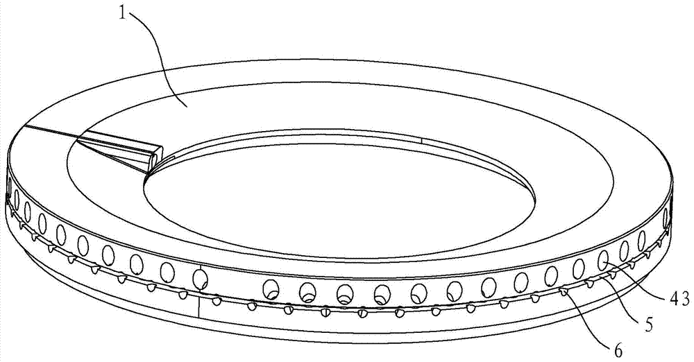
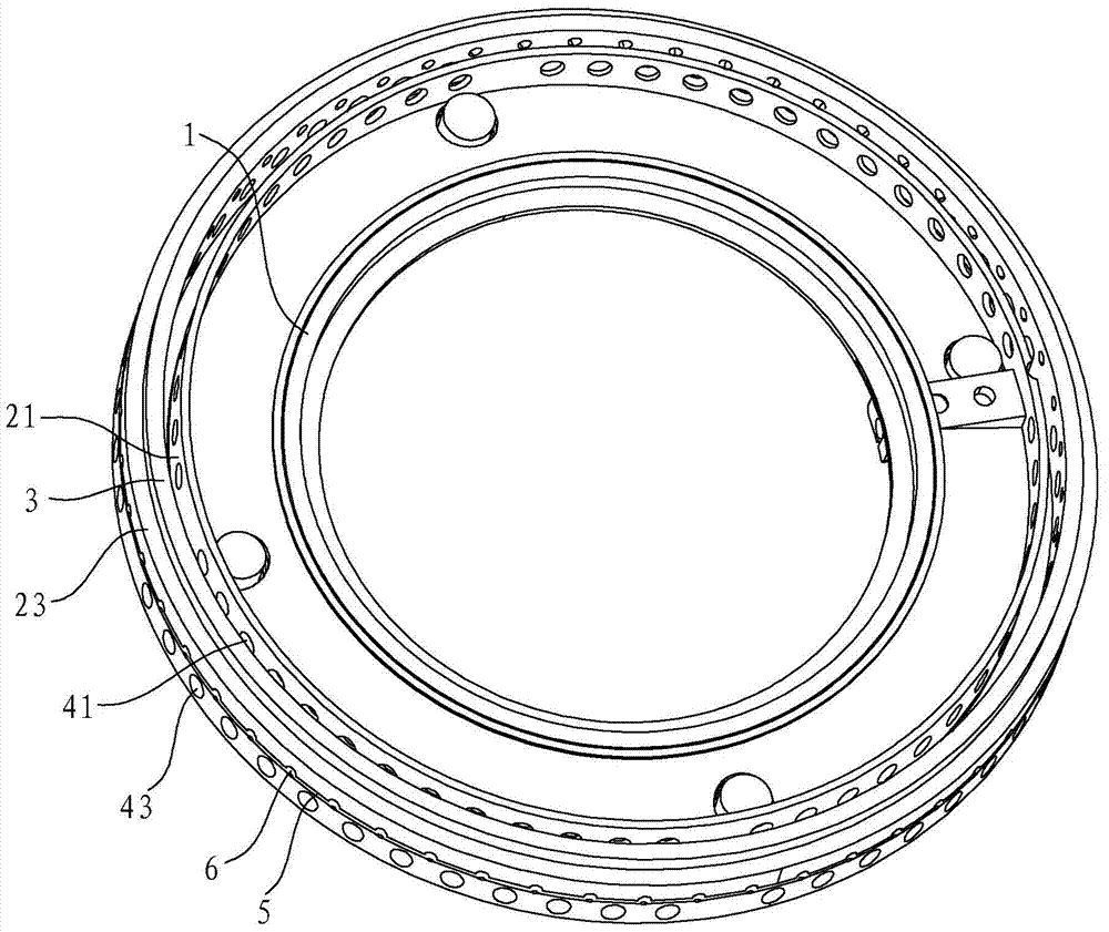
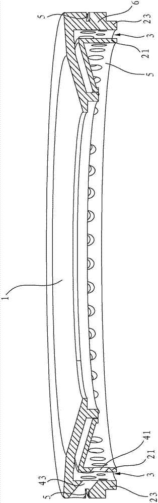
[0025] Such as Figure 1 to Figure 3 As shown, the burner fire cover for a gas cooker in this embodiment includes a fire cover body 1 , and the fire cover body 1 has double-layer annular side walls, specifically an inner annular side wall 21 and an outer annular side wall 23 . There is a gap between the inner annular side wall 21 and the outer annular side wall 23 to form a buffer layer 3, and the inner layer of fire holes 41 are distributed along the circumferential direction on the inner annular side wall 21, and the outer annular side wall 23 There are outer layer fire holes 43 distributed along the circumferential direction, the outer layer fire holes 43 correspond to the inner layer fire holes 41 one by one and the corresponding fire holes are arranged coaxially, thereby reducing the gas outlet resistance of the gas. And, the aperture of outer layer fire hole 43 is greater than the aperture of corresponding inner layer fire hole 41, thereby makes inner layer fire hole int...

Embodiment 2

[0029] Such as Figure 5 with Image 6 As shown, the fire cover body 1 of the burner fire cover in this embodiment has three layers of annular side walls, specifically the inner layer annular side wall 21, the middle layer annular side wall 22 and the outer layer annular side wall 23, the inner layer annular side wall There are gaps between the wall 21 and the middle annular side wall 22 and between the middle annular side wall 22 and the outer annular side wall 23 to form the buffer layer 3 . On the inner annular side wall 21, there are inner layer fire holes 41 distributed along the circumferential direction, on the middle layer annular side wall 22, there are intermediate layer fire holes 42 distributed along the circumferential direction, on the outer annular side wall 23 along the circumferential direction Outer layer fire holes 43 are distributed. The inner layer fire hole 41, the middle layer fire hole 42 and the outer layer fire hole 43 correspond one by one and the ...


PUM


Abstract

The invention discloses a burner fire cover used for a gas cooking appliance and a burner with the fire cover. The burner fire cover comprises a fire cover body. The fire cover body comprises annular side walls with fire holes. The burner fire cover is characterized in that at least two annular side walls are arranged, the corresponding fire holes are formed in each layer of annular side wall, and a gap is reserved between every two adjacent annular side walls to form a buffering layer. Compared with the prior art, the burner fire cover has the advantages that the buffer layers are formed between the adjacent side walls, after gas is buffered through the buffering layers in the process of flowing out of the fire holes in the outer layer annular side wall from the fire holes in the inner layer annular side wall, the blow-off limitation can be extremely increased, the back-fire limitation can be extremely reduced, and in other words, the adaptability of the gas can be improved on the premise of not increasing the depth of the fire holes; accordingly, according to the burner with the burner fire cover, gas in a gas mixing chamber of the burner can sequentially pass the gas mixing cavity and the fire holes in the inner layer annular side wall and then enters the buffering layer on the innermost side, and the adaptability of gas is improved after buffering is sequentially conducted through the multiple buffering layers.

Description

technical field [0001] The invention relates to a burner for a gas cooker, in particular to a burner fire cover for a gas cooker and a burner using the fire cover. Background technique [0002] The burner fire cover structure of existing gas cooker is generally annular fire cover, and it is made of annular top wall and annular side wall, and the bottom of annular fire cover is formed with annular groove, and the annular side wall of annular fire cover is opened along its circumferential direction. There are several main fire holes. In order to improve the gas applicability of the burner, when designing the burner, the thickness of the annular side wall of the fire cover is usually designed to be relatively thick, so that the depth of the fire hole can be increased accordingly, so that the fire limit is increased and the The tempering limit is reduced. However, when the thickness of the fire cover is increased, the weight of the fire cover will increase, which will lead to ...

Claims


Application Information

Patent Timeline
IPC IPC(8): F23D14/56F23D14/02
CPCF23D14/02F23D14/56
Inventor 褚武建郑军妹茅忠群诸永定
Owner NINGBO FOTILE KITCHEN WARE CO LTD
Why Eureka
Try Eureka