
A constant temperature control method for automatic temperature control heating water circulation

A technology of constant temperature control and water circulation, applied in water heaters, fluid heaters, heating or cooling equipment, etc., can solve the problems of difficult to maintain constant water temperature and uneven heating of heat sources, and achieve uniform acceleration of water temperature, high temperature control accuracy, and overcome Difficult to maintain a constant water temperature

Inactive Publication Date: 2017-01-25
GUILIN UNIVERSITY OF TECHNOLOGY
View PDF7 Cites 0 Cited by
  • Summary
  • Abstract
  • Description
  • Claims
  • Application Information

AI Technical Summary

Problems solved by technology

[0003] The purpose of the present invention is to overcome the disadvantages of uneven heating of traditional experimental heat sources and difficulty in maintaining constant water temperature, provide an automatic temperature control method for heating water circulation constant temperature control method, and provide a constant temperature heat source control method for indoor experiments on thermal physical characteristics of environmental rock and soil

Method used


Image

  • A constant temperature control method for automatic temperature control heating water circulation
  • A constant temperature control method for automatic temperature control heating water circulation
  • A constant temperature control method for automatic temperature control heating water circulation

Examples


Embodiment

[0018] A preferred embodiment of the present invention is described in detail as follows in conjunction with accompanying drawing:

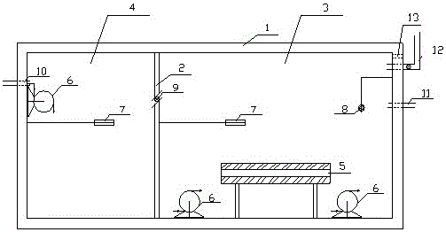
[0019] see Figure 1~3 , the automatic temperature control heating water circulation constant temperature heat source experimental device used in the present invention includes a heating water tank, a temperature and water circulation control device and a constant temperature hot water tank. The heating water tank uses a 20L vehicle-mounted incubator as the insulated box body 1, and the water tank is divided into the first water tank 3 and the second water tank 4 by the heat-insulating organic glass plate 2; the first water tank 3 has built-in electric heater 5, water circulation pump 6, water temperature Sensor 7 and liquid level sensor 8, the second water tank 4 built-in water circulation pump 6 and water temperature sensor 7, between the first water tank 3 and the second water tank 4 communicate through the connecting pipe 9 on the thermal ins...


PUM


Abstract

The invention discloses an automatic temperature control heating water circulation constant temperature control method. The automatic temperature control heating water circulation constant temperature control method uses an automatic temperature control heating water circulation constant temperature heat source experiment device which is composed of a heating water tank, a temperature and water circulation control device and a constant temperature hot water tank, wherein the heating water tank is divided into a first water tank and a second water tank, the first water tank and the second water tank are communicated through a connection pipe on a heat insulation organic glass plate, four holes are formed in the side wall of the heating water tank, a water adding pipe, a water outlet pipe, a water return pipe and a cable pipe are respectively installed in the four holes, the temperature and water circulation control device is composed of a power source switch, an outage protector, a temperature controller, a relay, a water circulation pump switch and an automatic water adding controller, and a water inlet pipe and a water outlet pipe are arranged at the top of the constant temperature hot water tank in butt fusion mode, and respectively connected with the water outlet pipe and the water return pipe of the heating water tank. The automatic temperature control heating water circulation constant temperature heat source experiment device is used to achieve automatic temperature control heating water circulation constant temperature control. The automatic temperature control heating water circulation constant temperature control method saves energy, and is safe, convenient to operate, high in temperature control accuracy, and wide in application range.

Description

technical field [0001] The invention relates to an automatic temperature control heating water circulation constant temperature control method, which belongs to the technical field of environmental geotechnical engineering measurement control. Background technique [0002] The thermophysical properties of rock and soil are a key content of environmental geotechnical engineering. In recent years, with the development of the economy, people have encountered a series of problems closely related to the thermophysical properties of rock and soil in various engineering constructions: ①The migration of heat and moisture in the soil during the mining of shallow ground energy; The impact of the "heat island" effect on soil; ③ soil heat transfer and diffusion in underground spaces such as subways and tunnels; ④ prevention of heat damage in mines, etc. In these engineering problems, on the one hand, the thermophysical properties of rock and soil affect the heat transfer process, and o...

Claims


Application Information

Patent Timeline
Patent Type & Authority Patents(China)
IPC IPC(8): F24H1/20F24H9/20B01L7/00
Inventor 曾召田赵艳林吕海波罗伯光韦昌富颜荣涛
Owner GUILIN UNIVERSITY OF TECHNOLOGY
Learn More