Helical fin pipe

A technology of helical finned tubes and fins, applied in the field of heat exchange equipment, can solve the problem that the heat exchange efficiency of the spiral finned tubes needs to be improved, etc., and achieve the effects of stable roots of sub-fins, enhanced air disturbance, and improved heat exchange efficiency.

Inactive Publication Date: 2015-01-21
TIANJIN TIANZONG CHEM EQUIP
View PDF0 Cites 22 Cited by
  • Summary
  • Abstract
  • Description
  • Claims
  • Application Information

AI Technical Summary

Problems solved by technology

It can be seen that the heat transfer efficiency

Method used


Image

  • Helical fin pipe

Examples


Embodiment Construction

[0010] The specific embodiments of the present invention will be described in detail below in conjunction with the accompanying drawings.

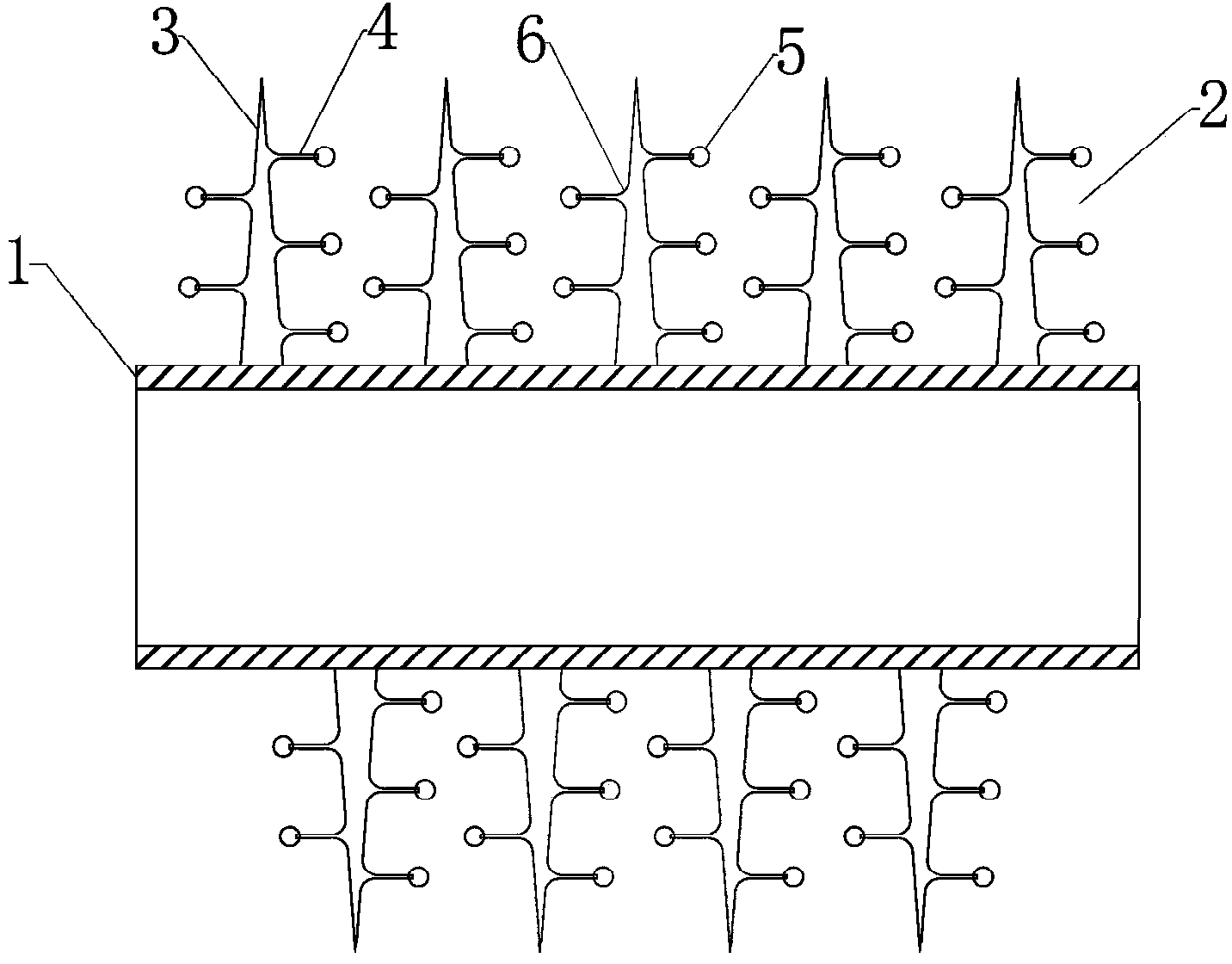
[0011] Such as figure 1 As shown, a spiral fin tube includes a base tube 1 and a fin 2. The fin 2 includes a main fin 3 and an auxiliary fin 4, and the auxiliary fin 4 includes an auxiliary fin end 5 and an auxiliary fin The fin root 6, the fin 2 is spirally welded to the outer surface of the base tube 1, the auxiliary fin 4 is fixedly connected to the main fin 3 through the auxiliary fin root 6, and the auxiliary fin root of the auxiliary fin is connected to The joint of the main fin is arc-shaped, and the end of the auxiliary fin of the auxiliary fin is spherical.

[0012] Using this spiral fin tube, when air passes through the fin 2, the boundary layer formed between the air and the surface of the fin 2 is destroyed by the sub-fin 4. The auxiliary fins 4 and the auxiliary fins 4 on the adjacent main fins 3 are arranged in a staggered arran...


PUM


Abstract

The invention provides a helical fin pipe which comprises a base pipe and fins. The fins comprise main fin bodies and auxiliary fin bodies, the auxiliary fin bodies comprise auxiliary fin body ends and auxiliary fin body roots, the fins are welded to the outer surface of the base pipe in a spiral mode, and the auxiliary fin bodies are fixedly connected with the main fin bodies through the auxiliary fin body roots. The auxiliary fin bodies promoting air to form turbulence are arranged on the fins of the helical fin pipe, so that the heat exchange area is increased while the heat exchange efficiency is improved.

Description

Technical field [0001] The invention belongs to the field of heat exchange equipment, and in particular relates to a spiral fin tube. Background technique [0002] In order to improve heat exchange efficiency, increase energy utilization, reduce emissions, and strengthen heat exchange has always been an eternal topic in the energy field. In order to enhance heat exchange, the fin pitch of the finned tube is usually very small, and the fin area can account for more than 85% of the total heat exchange area. Therefore, improving the heat exchange efficiency of the fins will improve the heat exchange efficiency of heat exchange equipment and reduce production. Cost is crucial. [0003] In the current existing heat exchange equipment, the spiral finned tube is widely used because it has a greater improvement in the enhanced heat transfer effect of the extended heating surface compared with the traditional finned tube. However, because the fin surface is smooth, the air is When passing...

Claims


Application Information

Patent Timeline
IPC IPC(8): F28F1/36F28F1/38
Inventor 丰金亭
Owner TIANJIN TIANZONG CHEM EQUIP
Why Eureka
Try Eureka