Touch panel and touch display panel

A technology of touch display and touch panel, which is applied in the direction of instruments, electrical digital data processing, digital data processing components, etc. Reduced brightness, uniform light transmittance, reduced color difference and brightness difference

Inactive Publication Date: 2015-01-21
WINTEK CORP
View PDF4 Cites 3 Cited by
  • Summary
  • Abstract
  • Description
  • Claims
  • Application Information

AI Technical Summary

Problems solved by technology

In this way, when the touch panel is arranged on the display surface of the display, the pattern of the transparent electrodes will affect the picture displayed on the display, thus causing the touch display device to fail to display a clear picture

Method used


Image

  • Touch panel and touch display panel
  • Touch panel and touch display panel
  • Touch panel and touch display panel

Examples


Embodiment Construction

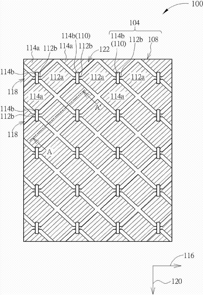
[0063] Please refer to Figure 1A and figure 2 , Figure 1A Shown is a top view of the touch panel of the first embodiment of the present invention, and figure 2 for along Figure 1A Sectional view of section line A-A'. like Figure 1A and figure 2 As shown, the touch panel 100 of this embodiment includes a substrate 102 , a touch sensing component 104 and a first optical matching layer 106 . Wherein, the touch sensing component 104 is disposed on one side of the substrate 102 and is used for sensing a position where a touch object, such as a finger or a stylus, touches the touch panel 100 . The first optical matching layer 106 is disposed on and covers one side of the substrate 102 . In this embodiment, the substrate 102 is disposed between the touch sensing element 104 and the first optical matching layer 106 . That is to say, the touch sensing element 104 and the first optical matching layer 106 are respectively disposed on two opposite sides of the substrate 102 , b...


PUM


Abstract

The present invention provides a touch panel. The touch panel includes a substrate, a touch sensing device, and an optical matching layer. The touch sensing device is disposed on one side of the substrate, and includes an electrode pattern. The electrode pattern includes silver or silver alloy. At least one side of the substrate has the optical matching layer disposed thereon.

Description

technical field [0001] The invention relates to a touch panel and a touch display panel, in particular to a touch panel and a touch display panel with uniform light transmittance. Background technique [0002] Due to the characteristics of human-computer interaction, the touch panel has been widely used in the external input interface of the instrument. In recent years, with the wide application of consumer electronics products, there are more and more application products that combine touch functions with displays to form touch display devices, such as: mobile phones, satellite navigation systems (GPS navigator system), tablet PC (tablet PC), personal digital assistant (PDA) and notebook computer (laptop PC), etc. [0003] The existing touch panel is arranged on the display surface of the display, so the picture displayed on the display surface needs to pass through the touch panel to be displayed. Therefore, the touchpad needs to be made of transparent materials, so as n...

Claims


Application Information

Patent Timeline
Patent Type & Authority Applications(China)
IPC IPC(8): G06F3/041
CPCG06F1/1643G06F3/044G06F2203/04111G06F3/0412G06F3/0443G06F3/0446
Inventor 陈健忠陈永霖康恒达
Owner WINTEK CORP
Why Eureka
Try Eureka