Fluid distribution device

A liquid distribution device and fluid communication technology, used in packaging, transportation and packaging, fluid mixers, etc., can solve the problems of falling market competitiveness and increasing cost of dyeing machines, and achieve the effect of simple configuration

Inactive Publication Date: 2006-06-14
FALMER INVESTMENTS LTD
View PDF0 Cites 1 Cited by
  • Summary
  • Abstract
  • Description
  • Claims
  • Application Information

AI Technical Summary

Problems solved by technology

The use of a frequency inverter can reduce the problems associated with uneven fluid height in each dyeing machine, but its use usually results in an increase in the cost of the dyeing machine, which in turn leads to a loss of market competitiveness

Method used


Image

  • Fluid distribution device
  • Fluid distribution device
  • Fluid distribution device

Examples


Embodiment Construction

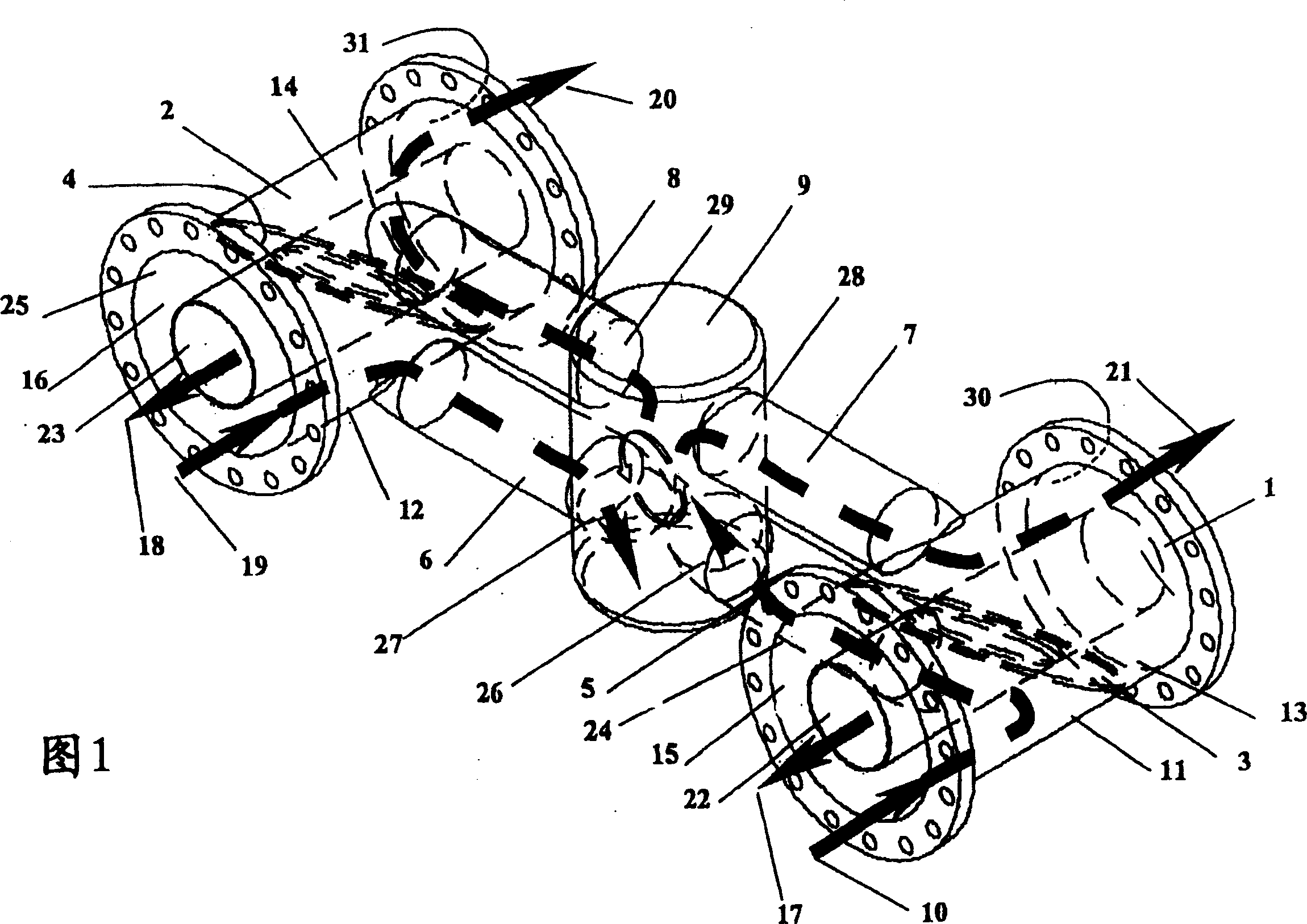
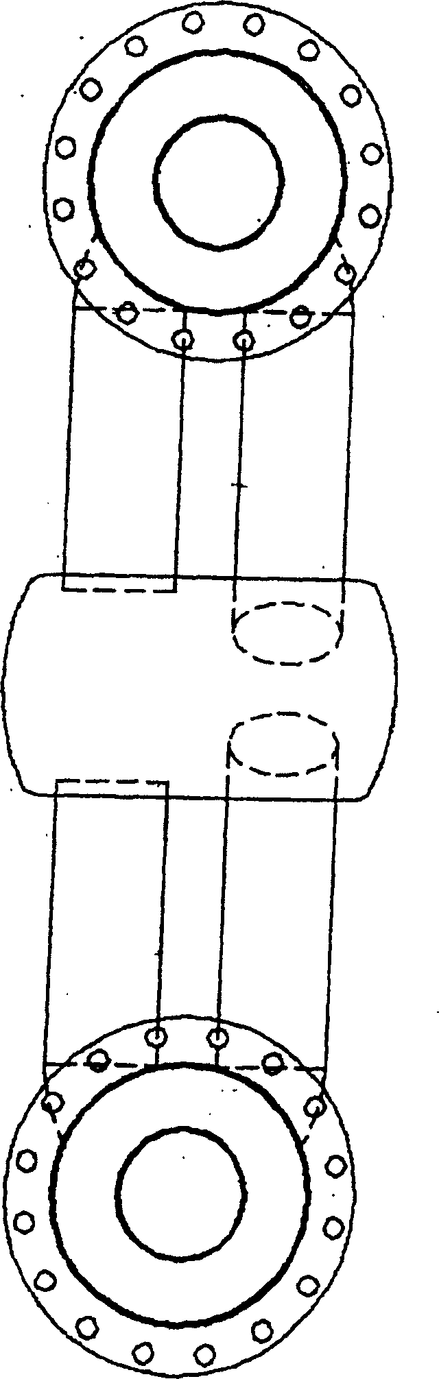
[0041] Referring now to Figures 1 to 4, a fluid distribution device is shown for distributing fluid to two textile dyeing machines.

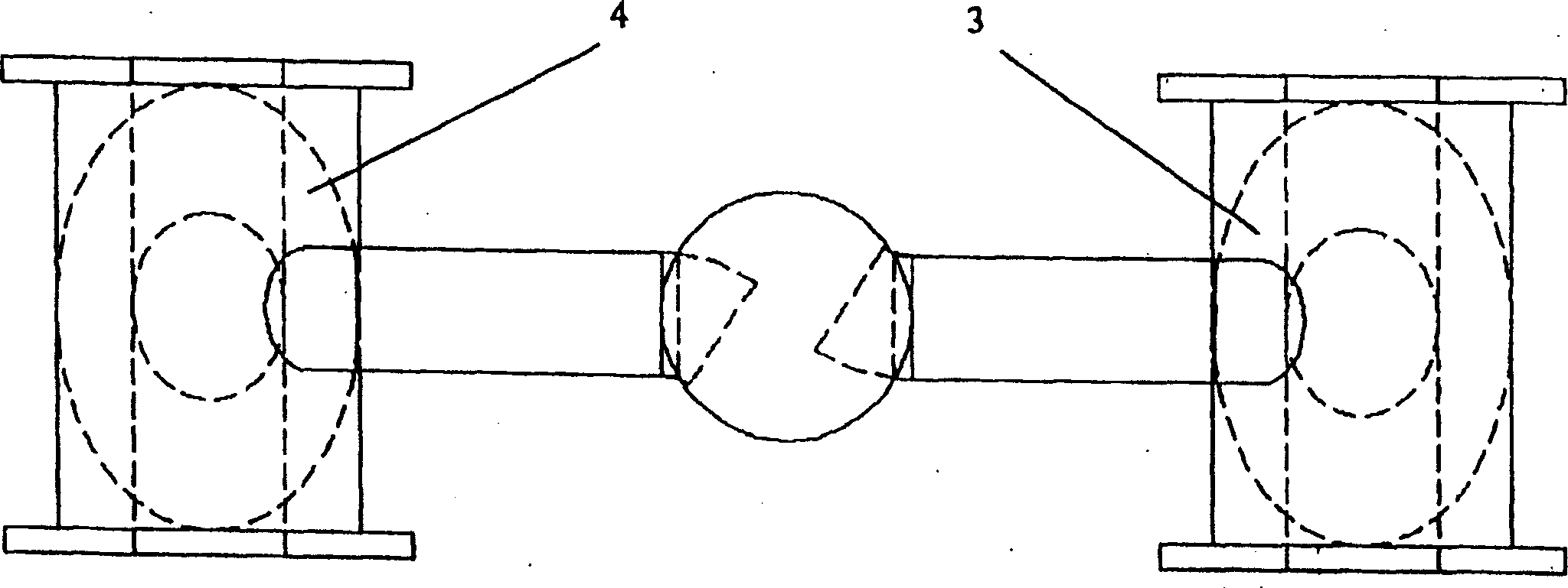
[0042] A container 9 is arranged in the middle of the two pipeline arrangements 1 , 2 and is in fluid communication with the two pipeline arrangements 1 , 2 . Each piping arrangement 1, 2 is formed by an inner tube 22, 23 and an outer tube 24, 25 coaxially arranged such that an annular channel 15, 16 is formed between the inner tube and the outer tube . The outer walls of the inner tubes 22 , 23 and the inner walls of the outer tubes 24 , 25 form the walls of the annular channels 15 , 16 . The inner tubes 22, 23 form an inner channel.

[0043] A partition plate 3,4 fits in the inner pipe body 22,23 to divide the annular channel 15,16 into two chambers 11,12,13,14, namely, a front chamber 11,12 and a rear chamber Room 13, 14. The plates are inclined with respect to the longitudinal axis of the pipeline arrangement and are roughly elliptical in ...


PUM


Abstract

A fluid dispensing device comprising a container (9) having a plurality of inlet tubes (5,6) and a plurality of outlet tubes (7,8) to facilitate the distribution of fluid to A corresponding number of textile processing machines (not shown). Each inlet tube (5, 6) is arranged to receive fluid and deliver the fluid to the container (9). The fluids are mixed in the container (9) and then distributed from the container (9) via outlet pipes (7, 8) to each textile processing machine (not shown).

Description

technical field [0001] The present invention relates to a fluid distribution device, and more particularly to a fluid distribution device for distributing fluid to two or more textile processing machines (but not limited thereto). Background technique [0002] In the dyeing process of a whole batch of yarn packages, usually the number of yarn packages exceeds the capacity of a single dyeing machine. Therefore, it is necessary to divide the yarn packages into smaller batch sizes. Each smaller batch is then usually processed by a different dyeing machine. Differences in color and shade often occur between batches when different dyeing machines are used. [0003] In order to improve the consistency of the color and shade of the dyeing process, a connecting device is usually used to connect the piping systems of the two dyeing machines. Traditional coupling methods and coupling devices are especially suitable for machines with external piping. [0004] According to the conve...

Claims


Application Information

Patent Timeline
Patent Type & Authority Patents(China)
IPC IPC(8): F16L41/03D06B3/20D06B23/00D06B5/16
CPCD06B5/16F16L41/03B65D88/54B65D90/00D06B1/00F16L41/00F16L41/02B01F25/00
Inventor 徐達明
Owner FALMER INVESTMENTS LTD
Why Eureka
Try Eureka