Switch

A switch and switch key technology, which is applied in the direction of electric switches, electrical components, substation/power distribution device shells, etc., can solve the problems of difficult installation, insufficient space for installation tools, small installation distance, etc., and achieve the effect of reducing the operation process

Inactive Publication Date: 2015-01-21
李耀强 +1
View PDF6 Cites 0 Cited by
  • Summary
  • Abstract
  • Description
  • Claims
  • Application Information

AI Technical Summary

Problems solved by technology

Screws are usually used to fix the wires on the terminal posts on the switch. During the installation process, the following situations are often encountered: First, if the length of the reserved wires is short, the installation distance between the switch panel and the junction box is also small, making the installation tools Insufficient space for activities makes installation

Method used


Image

  • Switch
  • Switch
  • Switch

Examples


Example Embodiment

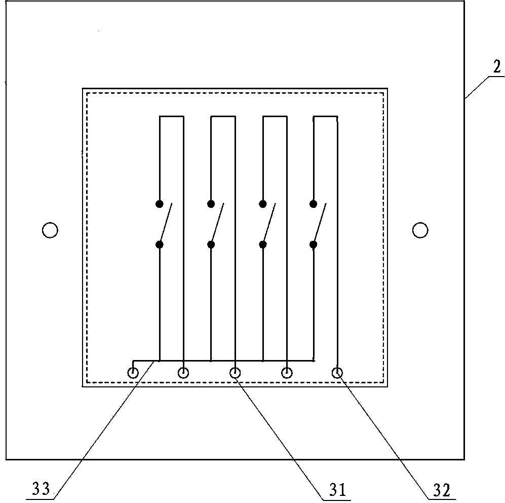
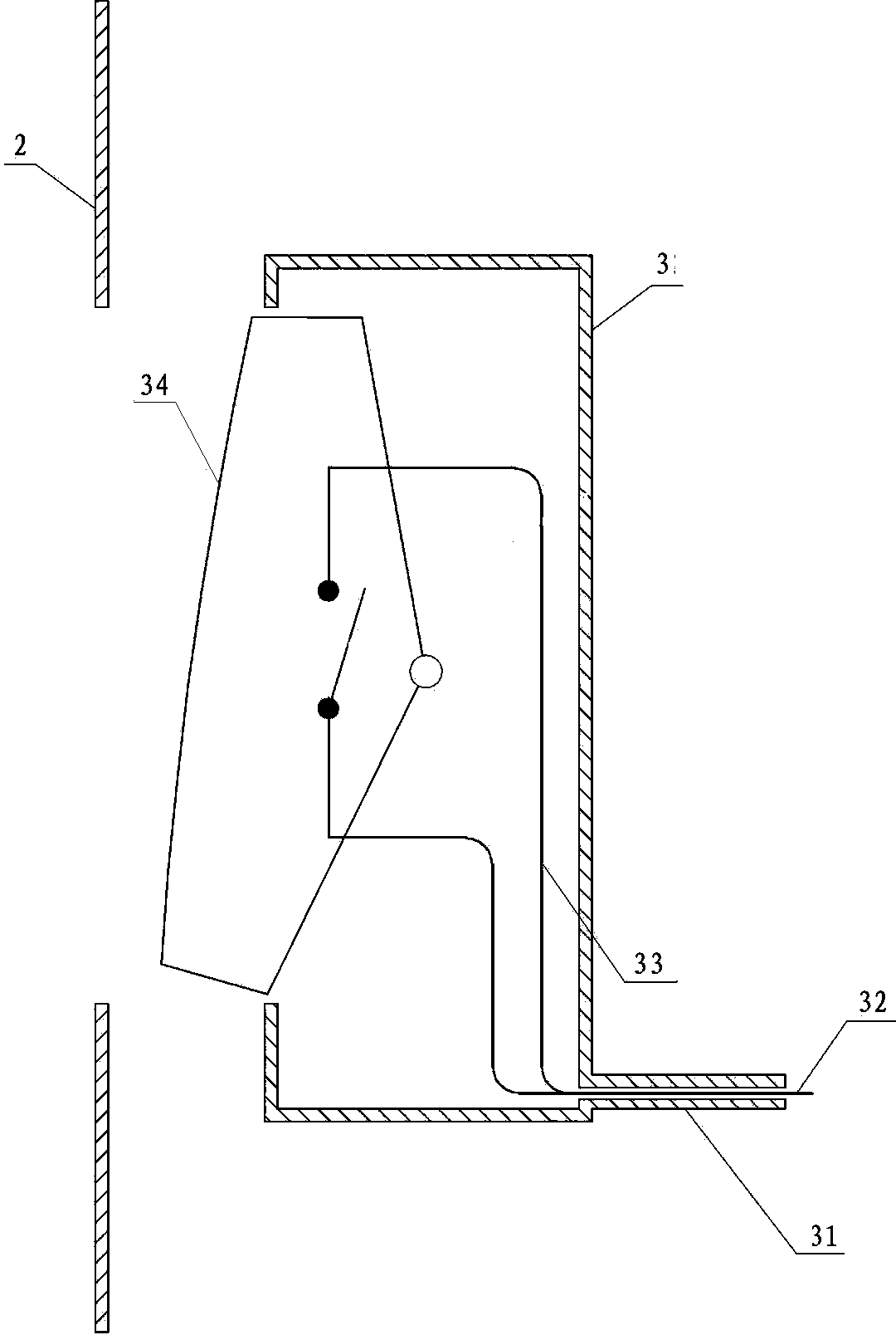
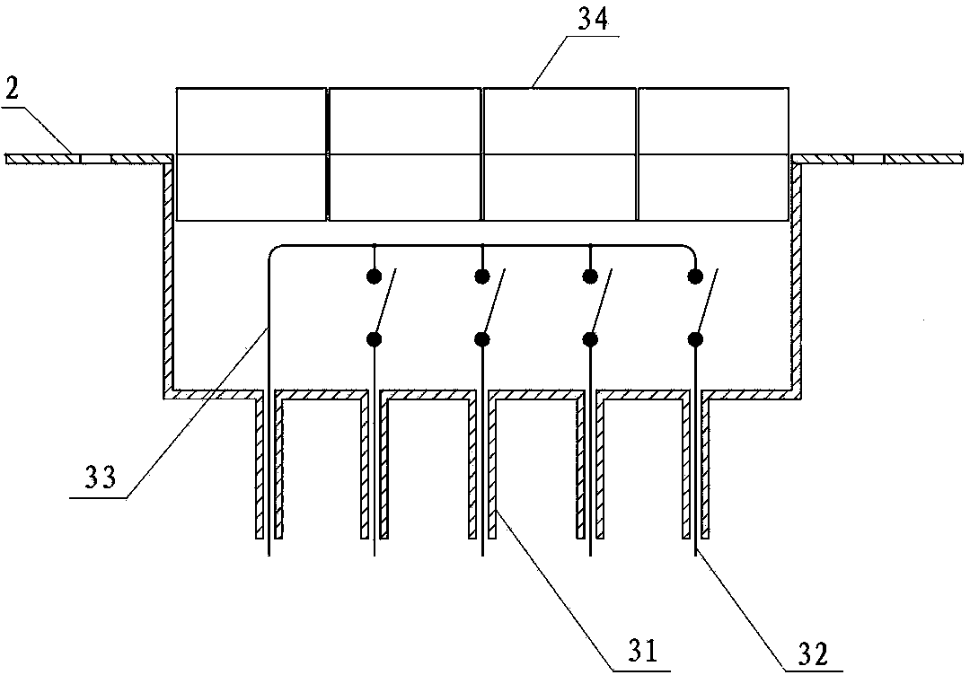
[0021] Such as Figure 1 to Figure 8 As shown, a switch consists of a junction box 1, a mounting panel 2 and a switch assembly 3. The mounting panel is fixed on the junction box, and the switch assembly 3 is installed in the opening reserved on the mounting panel 2. The switch assembly A switch key is set on the front, and a quick installation connector 4 is arranged in the junction box 1. The switch assembly includes more than one switch unit. The switch assembly is provided with an outwardly protruding plug post 31 on the side facing away from the mounting panel. A pin 32 is provided in the center of the plug-in column. One end of the pin in the switch assembly is connected to the connector 33, and the other end is exposed at the end of the plug-in column. The jack takes electricity; one end of the connecting body 33 is connected to the pin, and the other end is connected to one pole of the switch; the connecting body 33 and the pin 32 are made of conductive material; when the...


PUM


Abstract

The invention discloses a quick-mounting connector which mainly comprises a wiring base, a wiring terminal and a plug socket. Correspondingly, a fixing device of the wiring base is arranged in a wiring box. The quick-mounting connector can induce and pre-fix a wire, so that a complicated operation process during former connection with a switch/socket is saved, and quick mounting and dismounting of the switch/socket can be achieved.

Description

technical field [0001] The invention relates to a fast-installable plug-in switch, which belongs to the optimization technology of the switch. Background technique [0002] When the existing switch is connected with the wires drawn from the junction box, the direct connection method is mainly adopted, and the advantage is that the connection is simple and does not need to add additional equipment. Screws are usually used to fix the wires on the terminal posts on the switch. During the installation process, the following situations are often encountered: First, if the length of the reserved wires is short, the installation distance between the switch panel and the junction box is also small, making the installation tools Insufficient space for activities makes installation difficult; second, if the length of the reserved wires is longer, although the above problems are overcome, due to the limited space of the junction box, it is also difficult to put a large number of wires ...

Claims


Application Information

Patent Timeline
IPC IPC(8): H01H9/02H02B1/26
CPCH01H9/08H01H9/0264
Inventor 李耀强肖晟
Owner 李耀强
Why Eureka
Try Eureka