Charging control device and method

A charging control method and charging control technology, which are applied to circuit devices, battery circuit devices, and different battery charging, can solve problems such as long charging time, poor user experience, and inability to meet charging needs, and shorten charging time. , The effect of speeding up the charging speed

Active Publication Date: 2015-01-21
GUANGDONG OPPO MOBILE TELECOMM CORP LTD
View PDF4 Cites 39 Cited by
  • Summary
  • Abstract
  • Description
  • Claims
  • Application Information

AI Technical Summary

Problems solved by technology

However, due to the limitation of the specifications of the charging management chip, the existing charging method for the battery of the terminal device can no longer meet the charging demand of faster and higher current, resulting in long charging time and poor user experience

Method used


Image

  • Charging control device and method
  • Charging control device and method
  • Charging control device and method

Examples


Embodiment 1

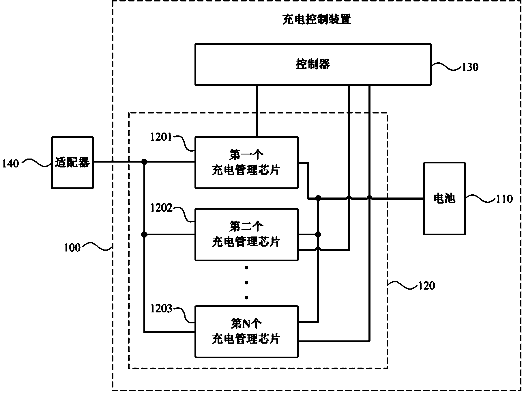
[0017] figure 1 It is a schematic structural diagram of a charging control device provided in Embodiment 1 of the present invention. see figure 1 , the charging control device 100 includes:

[0018] A battery 110, at least two charging management chips 120, and a controller 130;

[0019] The at least two charging management chips 120 include: a first charging management chip 1201 , a second charging management chip 1202 . . . an Nth charging management chip 1203 , where N is an integer greater than or equal to two.

[0020] Each charging management chip in the at least two charging management chips 120 is connected in parallel;

[0021] The input end of each of the at least two charge management chips 120 is used to connect to the current output end of the adapter 140, the output end of each charge management chip is connected to the battery 110, and is connected to the controller 130 through the bus ;

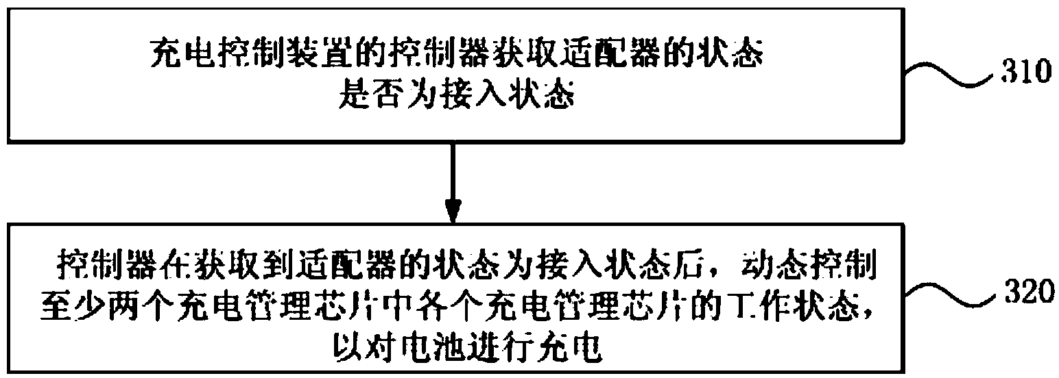
[0022] Wherein: the controller 130 is used to obtain whether the sta...

Embodiment 2

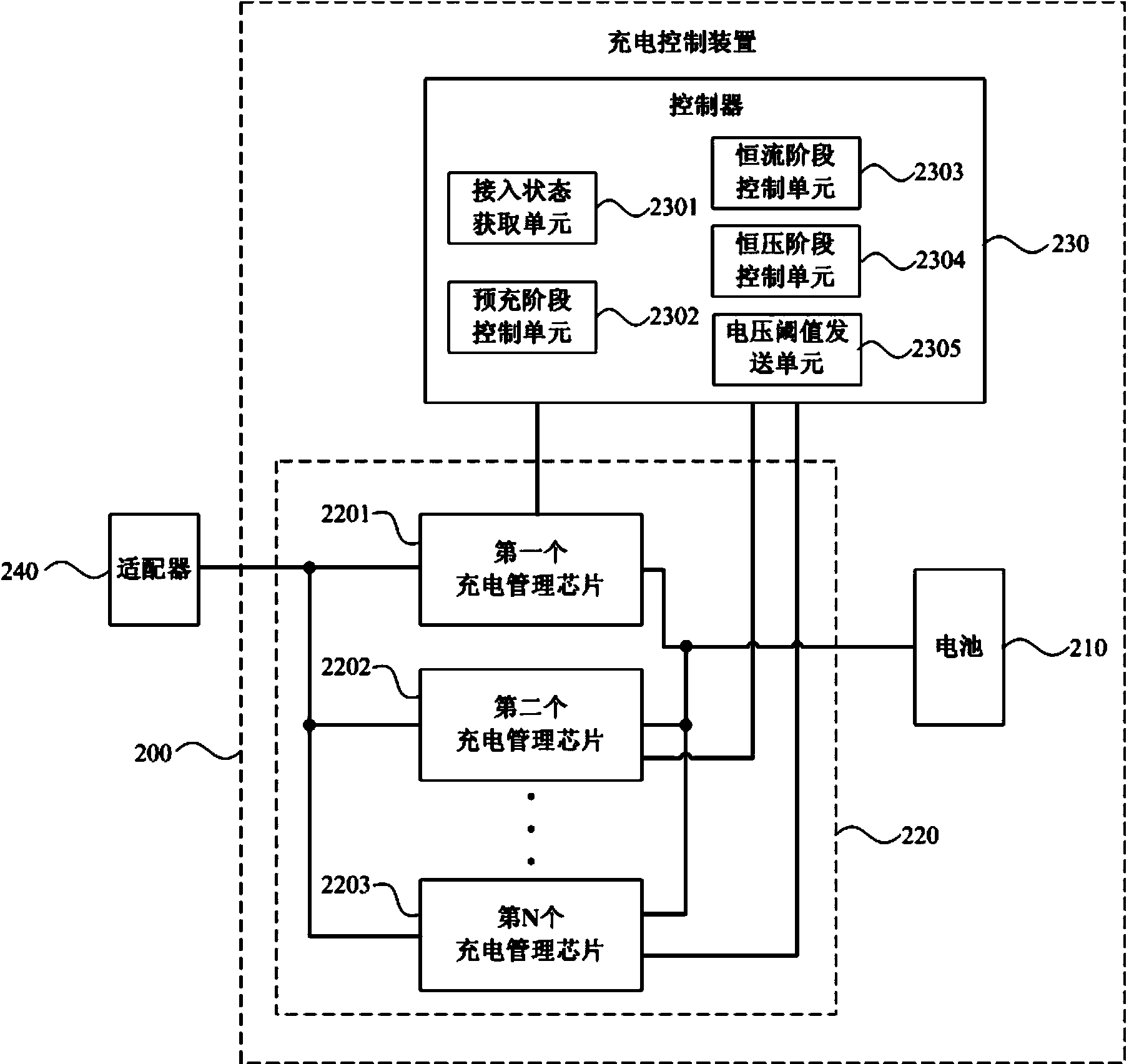
[0033] figure 2 It is a schematic structural diagram of a charging control device provided in Embodiment 2 of the present invention. In this embodiment, on the basis of the first embodiment above, the structure of the controller is further optimized. see figure 2 , the charging control device 200 includes:

[0034] A battery 210, at least two charging management chips 220, and a controller 230;

[0035] The at least two charging management chips 220 include: a first charging management chip 2201 , a second charging management chip 2202 . . . an Nth charging management chip, where N is an integer greater than or equal to two.

[0036] Each charging management chip of the at least two charging management chips 220 is connected in parallel;

[0037] The input end of each of the at least two charge management chips 220 is used to connect to the current output end of the adapter 240, and the output end of each charge management chip is connected to the battery 210 and connect...

Embodiment 3

[0057] This embodiment can provide a preferred example based on the foregoing embodiments. In this embodiment, the charging control device may be a mobile terminal. Wherein, the mobile terminal may be a smart phone, a personal digital assistant, a tablet computer, etc., which have a central processing unit and are powered by a lithium battery. The controller in the charging control device is the central processing unit CPU of the mobile terminal.

[0058] The constant current stage control unit 2303 in the controller 230 is specifically used for:

[0059] After receiving the first-stage switching instruction initiated by an interrupt when the main charging management chip switches from the pre-charging stage to the constant-current stage during the charging stage, according to the preset maximum constant-current value and at least two charging management chips 220 The maximum current parameter value determines the auxiliary charging management chip to be turned on in the con...


PUM


Abstract

The embodiment of the invention discloses a charging control device and method. The charging control device comprises a battery, at least two charging management chips and a controller, wherein the at least two charging management chips are connected in parallel, the input end of each of the at least two charging management chips is used for being connected with a current output end of an adapter, and the output end of each of the at least two charging management chips is connected with the battery and connected with the controller through a bus. The controller is used for acquiring whether the adapter is in an access state and dynamically controls the working state of each of the at least two charging management chips to charge the battery after the fact that the adapter is in the access state is acquired. According to the technical scheme, by connecting a plurality of charging management chips in parallel, the charging management chips are controlled dynamically by the controller, the charging speed can be quickened, the charging time can be shortened, and the charging requirement for quick and large current of the battery on a terminal device can be met.

Description

technical field [0001] Embodiments of the present invention relate to the technical field of charging, and in particular, to a charging control device and method. Background technique [0002] Currently, many terminal devices such as smartphones, tablet computers, and personal digital assistants are powered by batteries. With the rapid development of electronic technology, terminal equipment has more and more functions. For example, people can use terminal equipment for instant messaging, surfing the Internet, playing games, and watching videos. A large amount of power is consumed when using a terminal device. Therefore, the performance requirements for the battery and charging speed of the terminal equipment are also increased. [0003] In the prior art, when using an adapter (that is, a charger) to charge the battery on the terminal device, the current output by the adapter generally passes through the single-channel charging management chip connected to it, and then is ...

Claims


Application Information

Patent Timeline
Patent Type & Authority Applications(China)
IPC IPC(8): H02J7/00
CPCH02J7/0003H02J7/007
Inventor 冯红俊李家达邓南巍
Owner GUANGDONG OPPO MOBILE TELECOMM CORP LTD
Why Eureka
Try Eureka