Eureka AIR delivers breakthrough ideas for toughest innovation challenges, trusted by R&D personnel around the world.

Rail switch having a main track and a branch track

A technology of main rails and guide rails, which is applied in roads, tracks, laboratory appliances, etc., and can solve the problems of lower stability of basic rails

Active Publication Date: 2015-01-21
奥钢联软件系统有限责任公司 +1
View PDF8 Cites 2 Cited by
  • Summary
  • Abstract
  • Description
  • Claims
  • Application Information

AI Technical Summary

Problems solved by technology

[0005] In general, however, the already known solutions for reinforcing the cross-section of switch rails, especially for heavy-duty traffic, cannot be called completely adequate, since in some cases it is desirable to further improve the wear resistance of the switch rails resistance, and in addition reduced stability of the basic rail due to material reduction of the running edge of the basic rail

Method used


Image

  • Rail switch having a main track and a branch track
  • Rail switch having a main track and a branch track
  • Rail switch having a main track and a branch track

Examples


Embodiment Construction

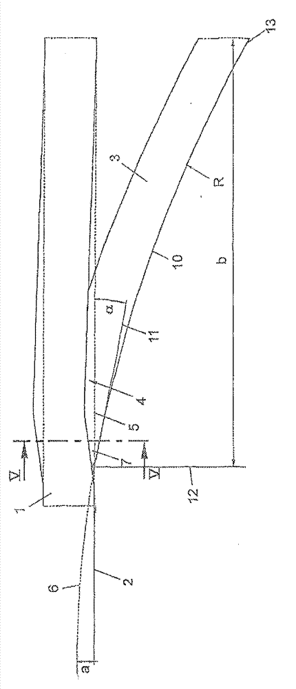
[0018] exist figure 1 Among them, 1 is used to represent the straight basic rail of the guide rail switch, and its running edge is represented by 2. The basic rail 1 basically has a straight guide rail course and accordingly has a straight running edge 2 . Generally speaking, the running edge of the guide rail is produced at the widest point of the guide rail head, which is measured at a predefined or standard-determined vertical distance from the running upper edge. Usually, the width of the base rail head is measured here at a vertical distance of 10 to 20 mm, in particular 14 mm, from the upper running edge.

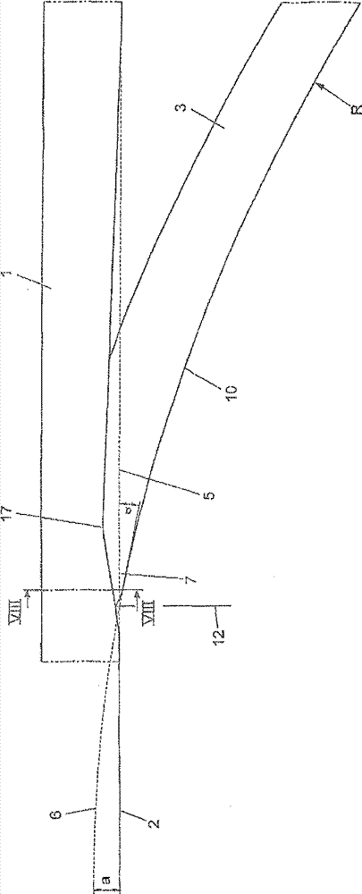
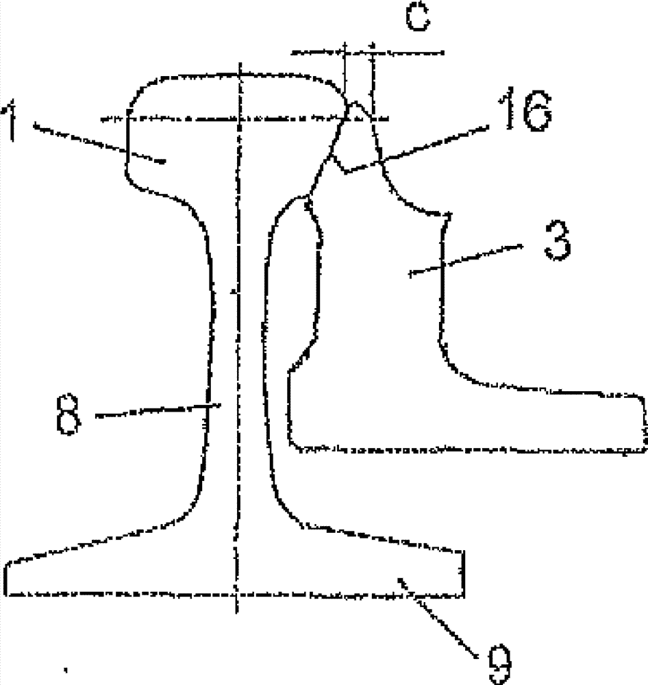
[0019] In the contiguous region of the switch rail 3 , the base rail 1 is offset from its straight course so that it has a projection 4 , whereby the running edge 2 also acquires a course in this region that deviates from the imaginary continuous straight course 5 . . In this case, the guide rail profile remains completely in the area of ​​the projection 4 , apart ...


PUM


Abstract

In a rail switch having a main track and a branch track, wherein each rail of each track is designed as a switch point (3) and can be moved to make contact with the respective outer rail (1), the outer rail (1) has, in the region of the switch point (3), a modified running edge profile, and the running edge (10) of the switch point (3) has a curved progression (6) for which the imaginary extension with the running edge (2) of the outer rail (1) has an overlap or an undercut.

Description

technical field [0001] The invention relates to a guide rail switch with a main rail and a branch rail, wherein each guide rail of each rail is designed as a point rail and can be moved to fit the respective base rail. Background technique [0002] When the switch is being driven over, high forces and in particular high lateral forces act on the guide rail, depending inter alia on the radius of curvature and the deflection angle of the switch, the speed at which the switch is being driven over, and the axle load. This transverse force has to be largely taken up by the switch rail, wherein especially in the case of a single inner curve switch in which the branch track diverges from the curved main track towards the inside of the curve, due to high inertia forces or centrifugal forces it can Particularly high loads were observed. This leads to increased wear of the switch rails, thereby greatly reducing the service life. In addition to this, modern switches must be able to b...

Claims


Application Information

Patent Timeline
Patent Type & Authority Applications(China)
IPC IPC(8): E01B7/02
CPCE01B7/02B01L13/02
Inventor J.格索达姆H.奧斯伯格
Owner 奥钢联软件系统有限责任公司
Why Eureka
Eureka Blog
Learn More