
Flowmeter pipeline dredging device

A flow tube and metering tube technology, applied in the field of flowmeter pipeline dredging devices, can solve the problems such as difficulty in dredging the U-shaped flow tube, inability to meet the cleanliness requirements of mass flowmeters, etc., and achieve the effect of convenient cleaning and smooth circulation

Inactive Publication Date: 2015-01-28
CHONGQING THRIVE CHEM
View PDF0 Cites 0 Cited by
  • Summary
  • Abstract
  • Description
  • Claims
  • Application Information

AI Technical Summary

Problems solved by technology

However, according to the experiment, it takes about 3 days to unclog the solid asphalt blockage in the straight pipe section, but it is difficult to unclog the U-shaped flow tube
Because, although the solid asphalt here can be dissolved into viscous semi-solid asphalt, it is difficult to completely clean these viscous substances from the U-shaped pipe, even if it takes 15 days, the mass flowmeter cannot be realized. Cleanliness requirements

Method used


Image

  • Flowmeter pipeline dredging device

Examples


Embodiment Construction

[0016] Below in conjunction with accompanying drawing and embodiment the technical solution of the present invention is further described:

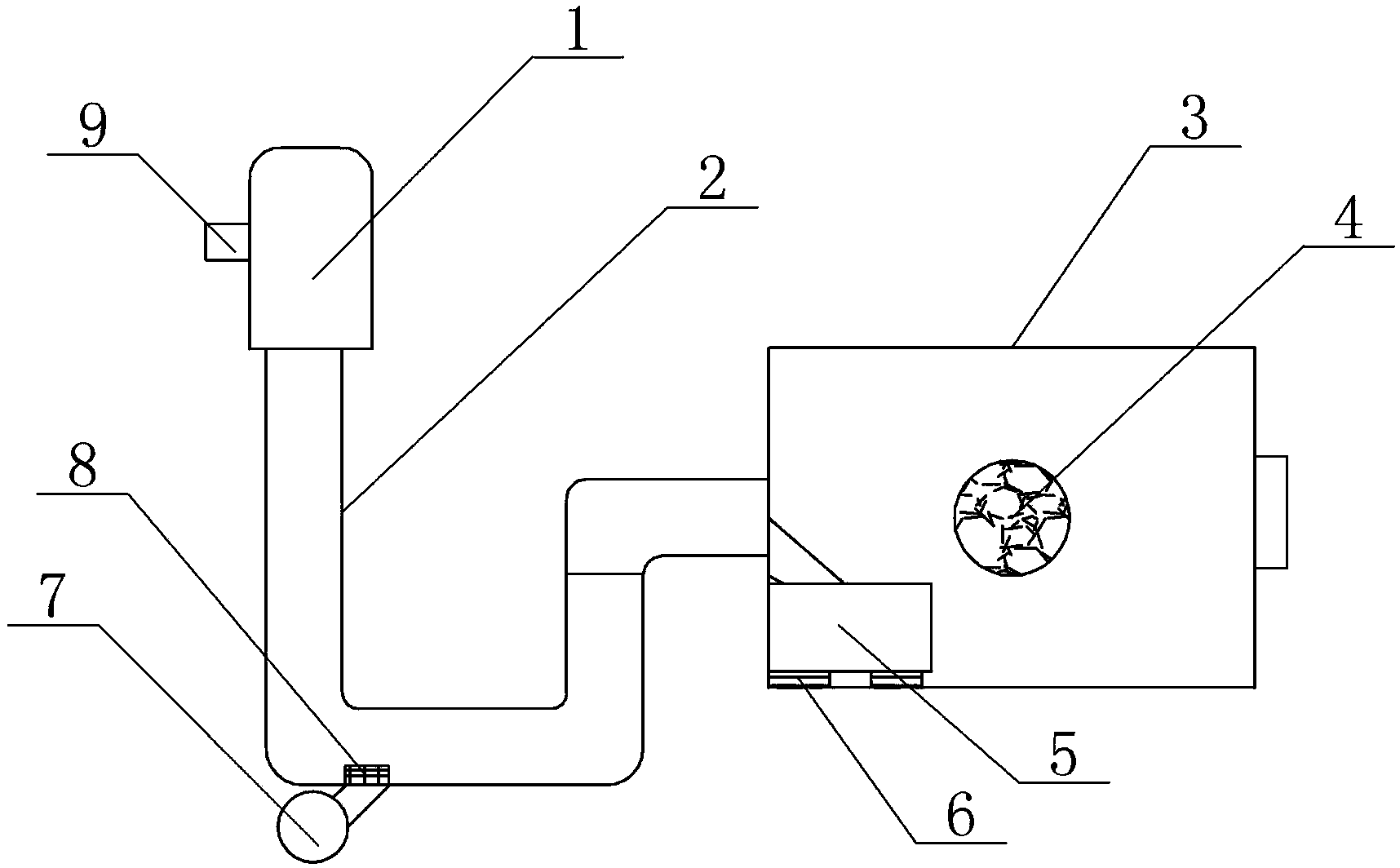
[0017] Such as figure 1 As shown, the present invention provides a flowmeter pipeline dredging device, including a flushing tank 1 connected to the inlet of the U-shaped flow tube 2 and a buffer tank 3 connected to the outlet, and the other side of the buffer tank 3 is provided with a discharge port. The inlet of the buffer box 3 can be connected with the outlet of the U-shaped flow tube 2 by a pipeline, and a centrifugal fan 7 is arranged at the horizontal pipeline section of the U-shaped flow tube 2, and the horizontal pipeline section of the centrifugal fan 7 and the U-shaped flow tube 2 An aeration pipe 8 is set at the connection, the centrifugal fan 7 is placed outside the U-shaped flow tube, and the aeration tube 8 is placed on the inner wall of the U-shaped flow tube 2; Diaphragm pump 5, on the buffer tank 3, the inlet correspond...


PUM


Abstract

The invention relates to the technical field of chemical equipment, in particular to a flowmeter pipeline dredging device. The flowmeter pipeline dredging device comprises a washing tank connected with the inlet of a U-shaped flow tube and a buffer box connected to the outlet of the U-shaped flow tube. A discharge outlet is formed in the other side of the buffer box. A centrifugal fan is disposed at the horizontal tube section of the U-shaped flow tube. An aeration tube is disposed at the connection of the centrifugal fan and the horizontal tube section. The centrifugal fan is disposed outside the U-shaped flow tube. The aeration tube is disposed on the inner wall of the U-shaped flow tube. A pneumatic membrane pump is disposed at the connection of the buffer box and the outlet of the U-shaped flow tube. A purifier is disposed at the center of the buffer box. By the flowmeter pipeline dredging device, U-shaped pipeline blocking is prevented, and convenience in washing is achieved.

Description

technical field [0001] The invention relates to the technical field of chemical equipment, in particular to a flow meter pipeline dredging device. Background technique [0002] A mass flow meter for a measurement system, for example, a Coriolis mass flow meter usually consists of components such as flow tubes, transmitters, and sensors. With this mass flow meter, fluid passes through a U-shaped flow tube, which keeps the flow tube vibrating. [0003] The interaction between the Coriolis force generated by the fluid and the vibration force of the flow tube causes the flow tube to twist, and the twist is proportional to the mass flow rate of the fluid. It can be seen from this principle that the measured value of the flowmeter is related to the vibration of the flow tube, and the vibration of the flow tube is related to the dirt in the flow tube. [0004] Due to the presence of some chemical substances in the material, long-term use of the mass flowmeter will cause fouling o...

Claims


Application Information

Patent Timeline
IPC IPC(8): B08B9/032B08B5/02B08B13/00
CPCB08B9/0321B08B9/035B08B13/00B08B2209/032
Inventor 赵华文
Owner CHONGQING THRIVE CHEM
Learn More