Adjustable position shearing machine

A technology for shearing machines and guide rails, which is applied in the direction of shearing devices, attachments of shearing machines, metal processing equipment, etc., and can solve problems such as inconvenient, laborious, and inability to move the position of the shearing machine

Inactive Publication Date: 2015-01-28
ANHUI FEIKAI ELECTRONICS TECH CO LTD
View PDF6 Cites 0 Cited by
  • Summary
  • Abstract
  • Description
  • Claims
  • Application Information

AI Technical Summary

Problems solved by technology

During the use of the shearing machine, the position is usually fixed, and the position of the shearing machine cannot be moved
When the object to be cut is rela

Method used


Image

  • Adjustable position shearing machine
  • Adjustable position shearing machine

Examples


Embodiment Construction

[0016] In order to make the object, technical solution and advantages of the present invention clearer, the present invention will be further described in detail below in conjunction with the accompanying drawings and embodiments. It should be understood that the specific embodiments described here are only used to explain the present invention, not to limit the present invention.

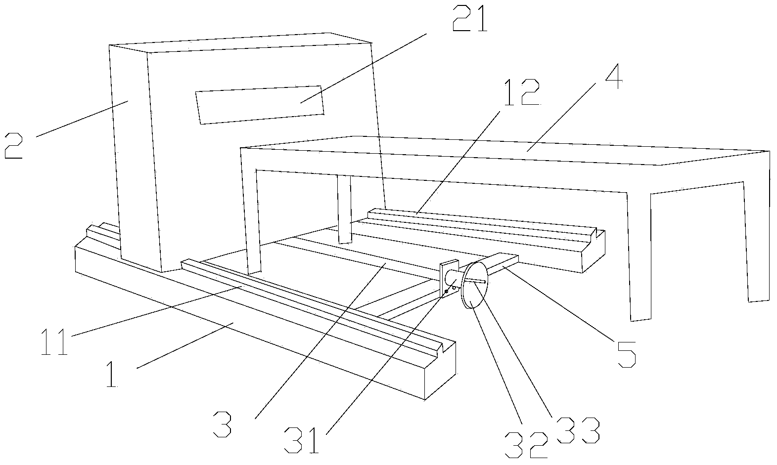
[0017] see figure 1 and figure 2 A position-adjustable shearing machine includes a base 1 , a long table 4 and a shearing machine main body 2 carried on the base 1 and capable of sliding relative to the base 1 . The long table 4 is located at the outlet 21 of the shearer main body 2 for receiving the objects sheared by the shearer main body 2 .

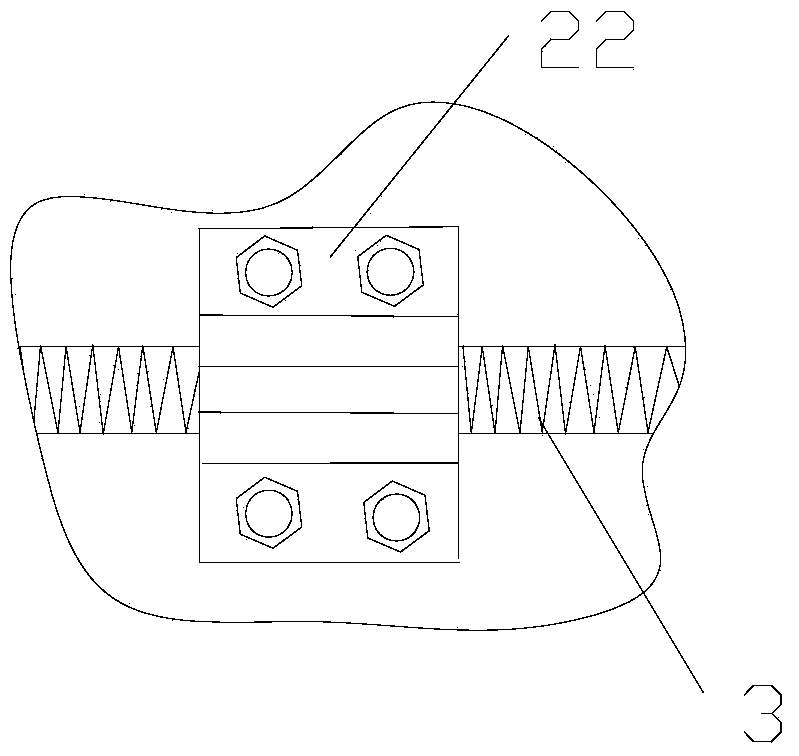
[0018] The base 1 is provided with two guide rails 11, 12 arranged in parallel, and the bottom surface of the shearer main body 2 is provided with two opening grooves (not shown) corresponding to the two guide rails 11, 12. The strip guide rails 11, 12...


PUM


Abstract

The invention discloses an adjustable position shearing machine. The machine comprises a base, and a shearing machine body which is borne by the base and can slide relative to the base; two parallel guide rails are arranged on the base; two opening grooves corresponding to the two guide rails are arranged in the bottom surface of the shearing machine body; the two guide rails guide the shearing machine body to slide on the base through the corresponding opening grooves; a lead screw parallel to the two guide rails is arranged between the two guide rails; a boss with a threaded hole is fixedly connected to the bottom surface of the shearing machine body; one end of the lead screw is fixedly connected with a handle through a bearing, and while the other end of the lead screw is equipped with threads for screwing and connecting with the boss; the lead screw is transmitted by the handle through the bearing and then transmits the shearing machine body through the boss, in order to enable the shearing machine body to slide on the base. With the adoption of the adjustable position shearing machine, the shearing machine body can slide on the base, thus the shearing machine body is conveniently moved, and the moving position can be accurately controlled.

Description

technical field [0001] The invention relates to a shearing machine, in particular to a position-adjustable shearing machine. Background technique [0002] The objects cut by the main body of the shearing machine are generally picked up manually. For the convenience of picking up the pieces, a long table is generally provided. The long table is located at the outlet of the main body of the shearing machine for receiving cut objects. During the use of the shearing machine, the position is usually fixed, and the position movement of the shearing machine cannot be realized. When the object to be cut is relatively large and the long table is not long enough, it is often necessary to move the shearing machine, usually by manually moving the shearing machine. convenient. Contents of the invention [0003] Aiming at the deficiencies of the existing solutions, the present invention proposes a position-adjustable shearing machine. [0004] The present invention is realized in su...

Claims


Application Information

Patent Timeline
IPC IPC(8): B23D33/00
Inventor 陈凯
Owner ANHUI FEIKAI ELECTRONICS TECH CO LTD
Why Eureka
Try Eureka