Probe moving position control device for ultrasonic flaw detection of wheel set and usage method

A technology for probe movement and control devices, which is applied in the direction of material analysis, measuring devices, and instruments using sound waves/ultrasonic waves/infrasonic waves. It can solve problems such as increased moving range, crack detection, and incomplete coverage, and achieves flexible positioning and adjustment. , avoid offset, reduce the effect of scratches

Active Publication Date: 2015-09-02
CRRC QIQIHAR ROLLING CO LTD
View PDF9 Cites 0 Cited by
  • Summary
  • Abstract
  • Description
  • Claims
  • Application Information

AI Technical Summary

Problems solved by technology

However, in the manual ultrasonic flaw detection method, the start position, end position and moving speed of the probe are controlled manually, so it can only be controlled by the proficiency and feeling of the flaw detector. For example, the moving speed of the probe is required to be between 20mm / s and 50mm / s In the meantime, as long as the flaw detectors have undergone at least 6 months of on-site strict training before taking up the job, the moving speed of the probe can basically guarantee to meet the requirements, but it is more difficult to accurately determine the starting position of the probe movement
If the starting position of the probe movement is not in place, it may cause missed detection of cracks, resulting in serious consequences
In response to this problem, on-site flaw detectors with high awareness of quality will try to increase the moving range of the probe to reduce the problem of incomplete coverage. However, the increase in the moving range will inevitably speed up the moving speed of the probe, which will also have a negative impact on the flaw detection effect.

Method used


Image

  • Probe moving position control device for ultrasonic flaw detection of wheel set and usage method
  • Probe moving position control device for ultrasonic flaw detection of wheel set and usage method
  • Probe moving position control device for ultrasonic flaw detection of wheel set and usage method

Examples


Embodiment Construction

[0016] The present invention will be described in detail below in conjunction with the accompanying drawings and embodiments.

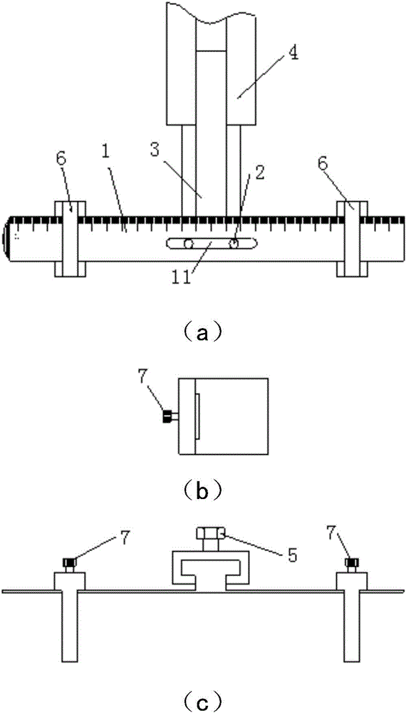
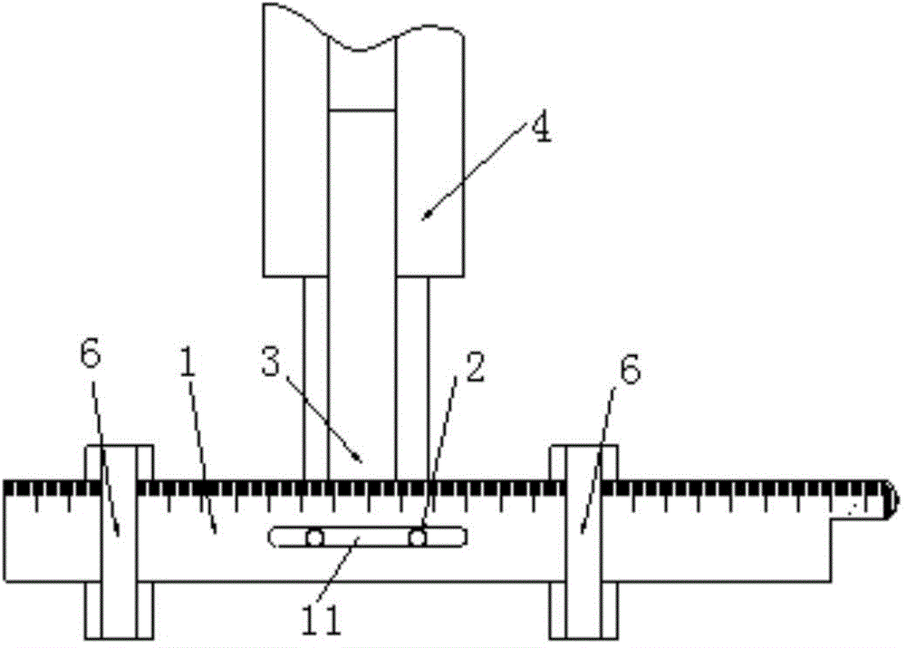
[0017] Such as figure 1 As shown, the probe moving position control device for wheel set ultrasonic flaw detection of the present invention includes a scaled substrate 1, more than one bolt nut 2, a dovetail slide bar 3, a dovetail chute 4, a fastening bolt 5, two Limiting moving plate 6 and two fastening screws 7. There is a long hole 11 horizontally in the middle of the base plate 1. The bolts and nuts 2 pass through the long hole 11 to fix one end of the dovetail slider 3 on the base plate 1, and the other end of the dovetail slider 3 is slid in the dovetail chute 4. , so that the connection position between the dovetail slide bar 3 and the dovetail chute 4 can be adjusted, and after the connection position is determined, the dovetail slide bar 3 is fixed in the dovetail chute 4 by fastening bolts 5 . Two limit moving plates 6 are respectively in...


PUM


Abstract

The invention relates to a probe movement position control device for wheel set ultrasonic flaw detection, and a using method of the device. The probe movement position control device comprises a base plate with scales, a bolt nut, a dovetail sliding rod, a dovetail sliding groove, a fastening bolt, limiting movable plates and fastening screws, wherein a long strip-shaped hole is formed in the middle of the base plate along the transverse direction; one end of the dovetail sliding rod is fixed on the base plate by the bolt nut which passes through the long strip-shaped hole; the other end of the dovetail sliding rod is arranged in the dovetail sliding groove in a sliding way and is fixed together with the fastening bolt; the two limiting movable plates respectively pass through the two ends of the base plate and are connected with the base plate by the fastening screws. According to the probe movement position control device for wheel set ultrasonic flaw detection, the position of the base plate can be adjusted along the transverse direction of a wheel set workpiece by adjusting the bolt nut, the height of the base plate can be adjusted along the longitudinal direction of the wheel set workpiece by adjusting the fastening bolt, and the positions of the two limiting movable plates on the base plate can be changed by adjusting the fastening screws, so that the probe movement position can be controlled. The probe movement position control device and the using method of the device are widely applied to the field detection of manual operation ultrasonic flaw detection of a wheel set in different industries.

Description

technical field [0001] The invention relates to a probe moving position control device and its use method, in particular to a probe movement position control device for wheel set ultrasonic flaw detection and its use method. Background technique [0002] The wheel set is an important part of the vehicle. The railway freight wheel set is composed of two parts: the axle and the wheel. Fatigue cracks will occur at the mating part of the axle and the wheel (the wheel seat insert) during use. If the fatigue cracks cannot be detected, Then the vehicle will cause a cold cut (broken axle) accident during the operation of the vehicle, and the consequences and hazards will be very serious. Therefore, during the inspection and maintenance of railway freight wheel sets, it is necessary to use ultrasonic flaw detection to inspect the fatigue cracks in the wheel seat inserts of the wheel sets. During ultrasonic flaw detection, angle probes with two angles are used to move a certain dista...

Claims


Application Information

Patent Timeline
Patent Type & Authority Patents(China)
IPC IPC(8): G01N29/265
Inventor 李艳琴金锋宋玉亮孙蕾刘喜双李大海许鸿斌胡松林闫保营陈子涛高国强
Owner CRRC QIQIHAR ROLLING CO LTD
Why Eureka
Try Eureka