
Bar shearing device

A shearing device and bar material technology, which is applied in the direction of shearing devices, shearing machine accessories, shearing machine equipment, etc., can solve the problems of waste of raw materials, uneven shearing, damage to blades, etc., and achieve good cross-section flatness , The effect of saving materials

Inactive Publication Date: 2015-01-28
高超 +1
View PDF6 Cites 3 Cited by
  • Summary
  • Abstract
  • Description
  • Claims
  • Application Information

AI Technical Summary

Problems solved by technology

[0003]In the existing shearing device for shearing bar stock, during the shearing process, the shearing of the upper and lower knives will cause a large deformation at the shearing point , it is a waste of raw materials. At the same time, when the bar is cut to a certain extent, it will break from the shearing place due to its own gravity, which will not only cause the shearing place to be uneven, but also may damage the blade.

Method used


Image

  • Bar shearing device
  • Bar shearing device
  • Bar shearing device

Examples


Embodiment Construction

[0024] The technical solution of the present invention will be further described below in conjunction with the accompanying drawings.

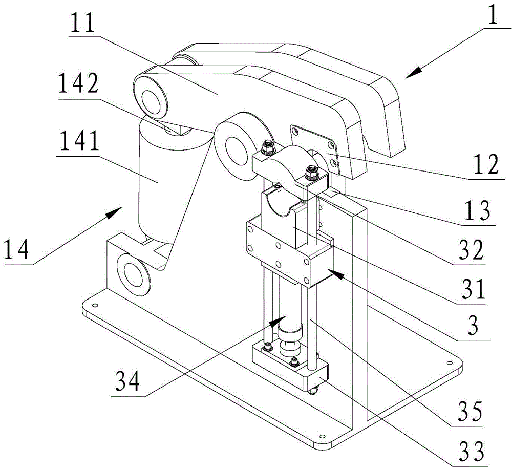
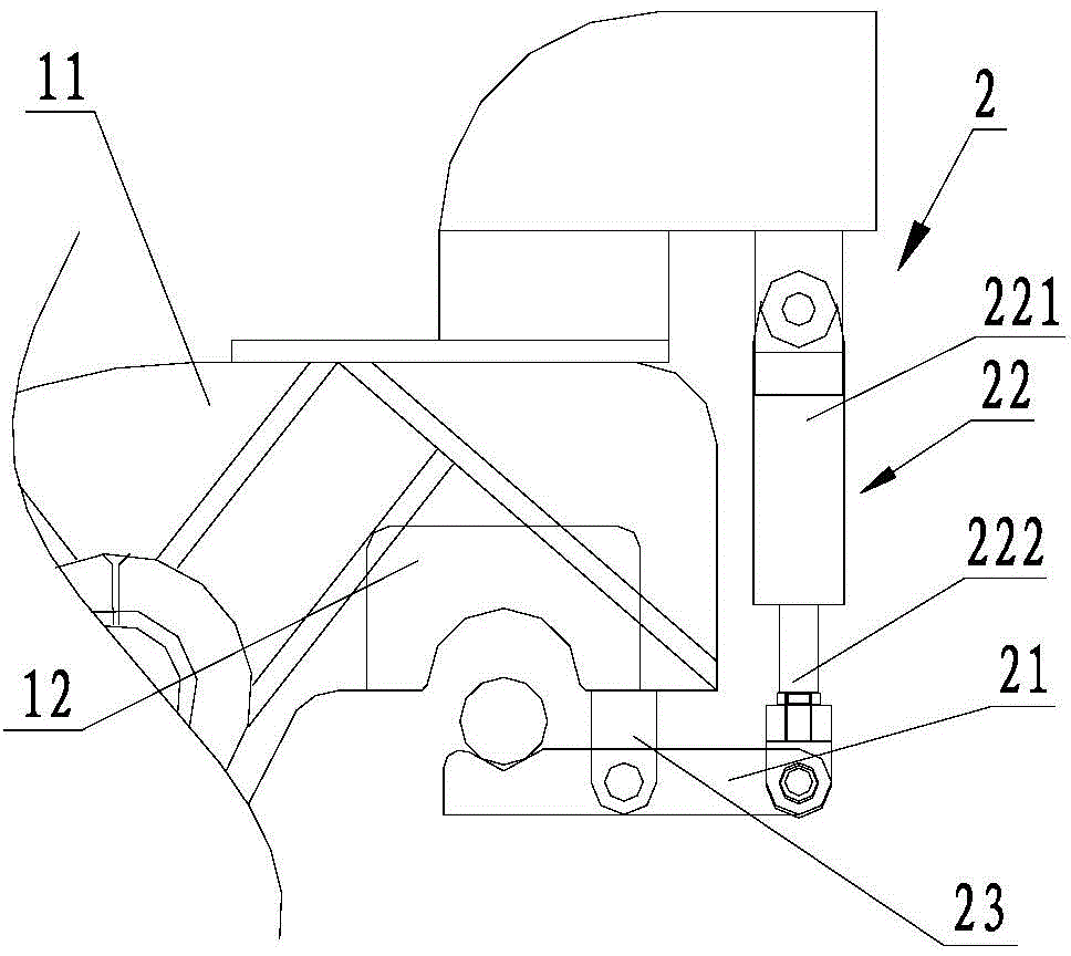
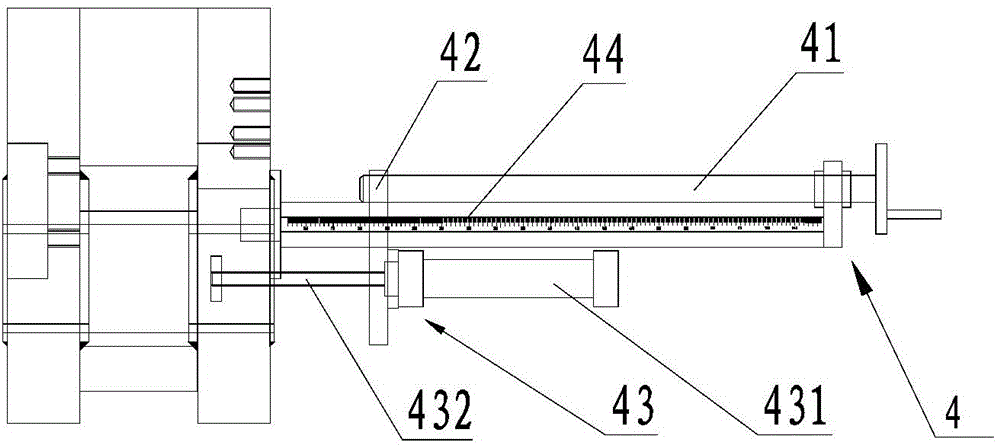
[0025] see figure 1 , figure 2 As shown, the above-mentioned shearing device for shearing the bar includes a fixed seat, a pressing mechanism 3 for pressing the bar to be sheared on the fixed seat, and a pressing mechanism 3 for pressing the bar to be cut. A shearing mechanism 1 for shearing the bar, a supporting mechanism 2 for supporting the bar when the shearing mechanism 1 is shearing, and a pressing mechanism 3 are located at the feeding port side of the bar.

[0026] This shearing mechanism 1 is located on the fixed seat, and the shearing mechanism 1 comprises the shearing arm 11 that is rotatably arranged on the frame, and one end of the shearing arm 11 is provided with an upper blade 12, and the frame is provided with the upper blade 12. Matching lower blade 13, the lower blade 13 has a concave blade surface, the bottom of t...


PUM


Abstract

The invention discloses a bar shearing device. The bar shearing device comprises a fixed seat, a pressing mechanism, a shearing mechanism and a supporting mechanism. The pressing mechanism is used for pressing to-be-sheared bars onto the fixed seat, the shearing mechanism is used for shearing the bars, and the supporting mechanism is used for supporting the bars. The pressing mechanism is positioned on a bar feeding port side, the shearing mechanism comprises a shearing arm rotatably arranged on the fixed seat, an upper blade is arranged at one end of the shearing arm, a lower blade matched with the upper blade is arranged on the fixed seat, the supporting mechanism comprises a supporting part, and the supporting part is rotatably arranged on the shearing arm and used for supporting the to-be-sheared bars. During shearing of the bars, the unsheared sides of the bars can be fixedly pressed by the pressing mechanism, and to-be-sheared portions of the bars can be supported by the supporting mechanism, so that higher stability of the bars during shearing is achieved, smoothness in shearing is guaranteed, high flatness of sections at sheared positions is achieved, and materials are well saved.

Description

[0001] technical field [0002] The invention relates to a bar shearing device. Background technique [0003] In the existing shearing device for shearing bars, during the shearing process, the shearing of the upper and lower knives will cause a large deformation at the shearing point, which is a waste of raw materials. At the same time, the bar is cut to a certain To a certain extent, it will break from the shearing place due to its own gravity, which will not only cause the unevenness of the shearing place, but also may damage the blade. Contents of the invention [0004] The object of the present invention is to provide a shearing device for bar stock. During the shearing process, the bar stock to be sheared can be stably compressed and supported, so that the shearing is more convenient and the deformation of the shearing place is small. , which saves materials better. [0005] In order to achieve the above object, the technical scheme adopted in the present invention...

Claims


Application Information

Patent Timeline
IPC IPC(8): B23D33/02B23D17/06
Inventor 施士清
Owner 高超
Learn More