
Laser cutting device capable of forming extendable controllable crack based on plasma and laser cutting method

A laser cutting and plasma technology, used in laser welding equipment, semiconductor devices, manufacturing tools, etc., can solve problems such as the inability of laser stealth cutting efficiency to meet relevant requirements and the expansion of wafer damage areas, so as to improve production efficiency and production quality. , The effect of improving cutting efficiency and improving flatness

Inactive Publication Date: 2020-04-24
WUHAN UNIV
View PDF5 Cites 3 Cited by
  • Summary
  • Abstract
  • Description
  • Claims
  • Application Information

AI Technical Summary

Problems solved by technology

However, as the demand for chips increases, the efficiency of laser stealth dicing cannot meet the relevant requirements. Therefore, improving the efficiency of laser stealth dicing is an urgent problem to be solved in the semiconductor industry
[0005] Generally speaking, the semiconductor industry improves the processing efficiency by increasing the laser energy to form a larger modified layer to reduce the number of stealth cuts, but this leads to the expansion of the damaged area inside the wafer

Method used


Image

  • Laser cutting device capable of forming extendable controllable crack based on plasma and laser cutting method
  • Laser cutting device capable of forming extendable controllable crack based on plasma and laser cutting method
  • Laser cutting device capable of forming extendable controllable crack based on plasma and laser cutting method

Examples


Embodiment Construction

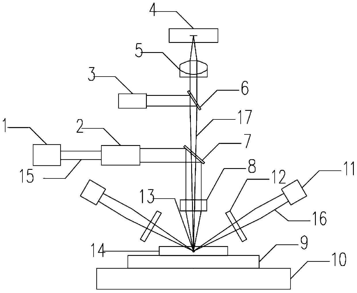
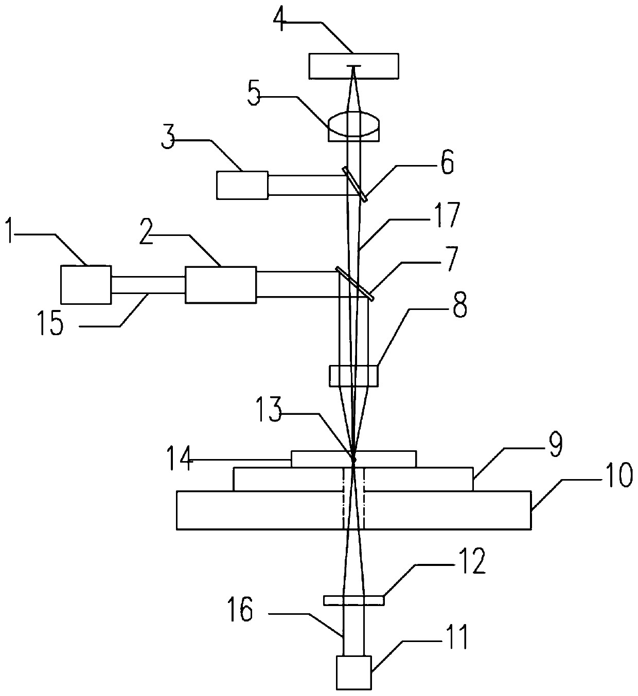
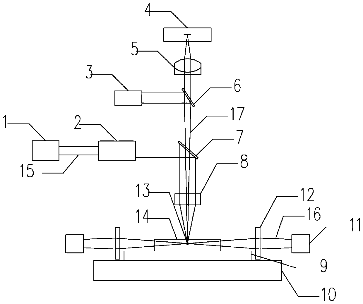
[0046] The plasma-based laser cutting device for expanding controllable cracks includes: a multi-axis mobile platform 9; an imaging system for acquiring surface images of the workpiece 14 processed on the multi-axis mobile platform 9; a stealth cutting device for generating laser beams 15, laser The beam 15 converges to the inside of the workpiece 14 to be processed to form a high-energy stealth cutting laser focal spot 13. The workpiece material at the focal spot absorbs energy and then vaporizes and ionizes to form plasma, which expands and impacts the material to form cracks; and one or more The auxiliary laser device is used to generate the auxiliary laser beam 16. The focus of the auxiliary laser beam 16 converges to the plasma and crack area inside the workpiece 14. After the plasma absorbs the energy of the auxiliary laser beam 16, it accelerates to expand, and further impacts the formed crack, making the crack expand. Since the crack is longer than that obtained by the...


PUM


Abstract

The invention discloses a laser cutting device capable of forming an extendable controllable crack based on plasma and laser cutting method. The laser cutting device comprises a multi-axis mobile platform (9), an imaging system, an invisible cutting device and one or more auxiliary laser devices, wherein the imaging system is used for acquiring a surface image of a to-be-machined workpiece (14) onthe multi-axis mobile platform (9), the invisible cutting device is used for generating a laser beam (15), the laser beam (15) converges into the to-be-machined workpiece (14) to make a workpiece material at an invisible cutting laser focal spot (13) be gasified and ionized to form the plasma, and the plasma expands and impacts the material to form the crack, the one or more auxiliary laser devices are used for generating an auxiliary laser beam (16), and the focal spot of the auxiliary laser beam (16) converges to a plasma and crack area inside the to-be-machined workpiece (14) to accelerateexpansion of the plasma to further impact the formed crack to make the crack be extended. According to the device and the method, by controlling the position and the energy of the auxiliary laser beam (16), the crack extension length and direction are controllable.

Description

technical field [0001] The invention belongs to the field of mechanical cutting and processing, and relates to a high-definition ultrafast laser stealth cutting technology, in particular to a plasma-based laser cutting device and method for extending controllable cracks. Background technique [0002] At present, the semiconductor industry widely uses mechanical dicing methods to cut wafers. Wafer mechanical dicing is the use of high-speed rotating cutting blades to directly divide the wafer. The advantage of mechanical cutting is that it is easy to operate and does not require high cutting equipment. However, mechanical cutting has many disadvantages. Firstly, mechanical dicing can easily cause chipping and breakage of the wafer; secondly, the scribing line of mechanical dicing is relatively large, causing unnecessary waste; finally, the blades used in mechanical dicing are easy to wear and need to be replaced frequently, resulting in high cost. Ultimately, these disadvan...

Claims


Application Information

Patent Timeline
IPC IPC(8): B23K26/53B23K26/08B23K26/06B23K26/03B23K26/70B23K101/40
CPCB23K26/032B23K26/0643B23K26/0648B23K26/0853B23K26/53B23K26/702B23K2101/40
Inventor 张臣刘胜王力恒程佳瑞
Owner WUHAN UNIV
Learn More