Refrigerator door body

A refrigerator door and door frame technology, which is applied to cooling fluid circulation devices, lighting and heating equipment, household appliances, etc., can solve the problems of high production cost and high cost of refrigerator doors, and improve production efficiency, production quality, and mold costs Reduction, production cost reduction effect

Active Publication Date: 2021-03-02
AUCMA
View PDF5 Cites 0 Cited by
  • Summary
  • Abstract
  • Description
  • Claims
  • Application Information

AI Technical Summary

Problems solved by technology

In the above various methods, each part that makes up the refrigerator door body is an injection molded part or an extruded part, so each part requires a specific injection mold or extrusion mold. Due to the high cost of the mold, the refrigerator door body production cost is high

Method used


Image

  • Refrigerator door body
  • Refrigerator door body
  • Refrigerator door body

Examples


Embodiment 1

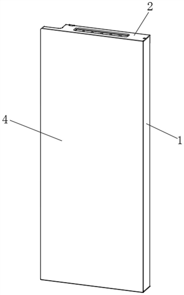
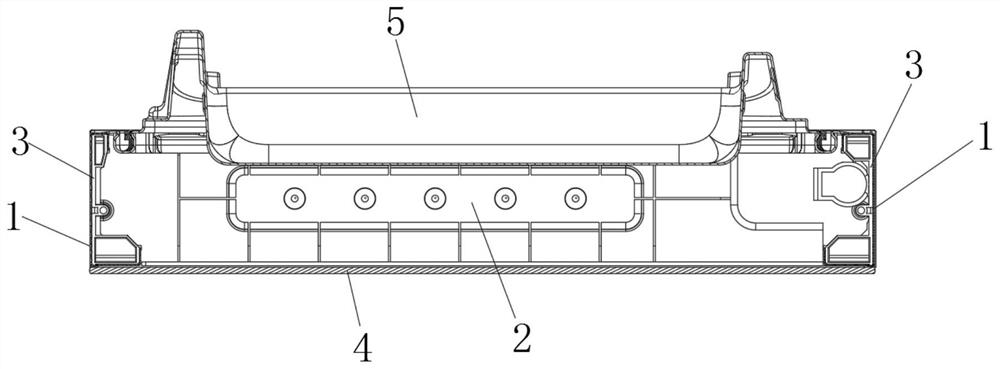
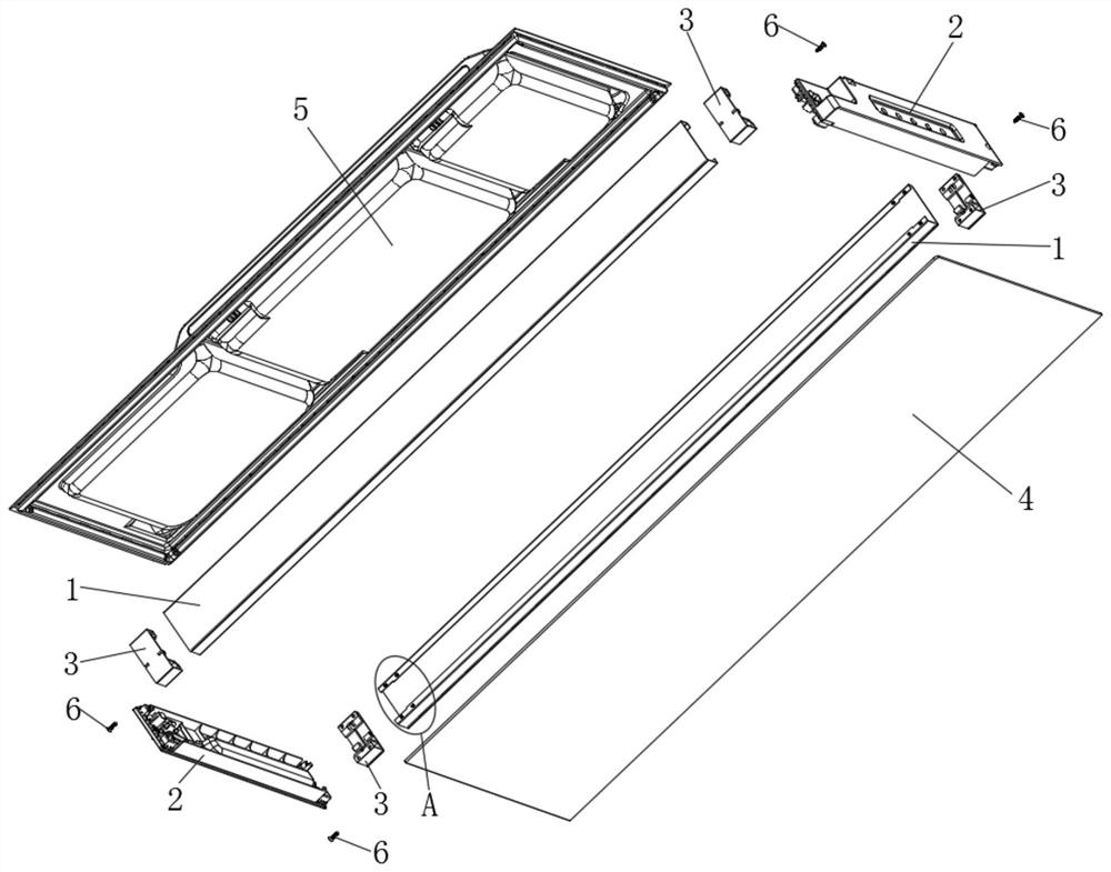
[0057] Such as Figure 1-3 As shown, a refrigerator door body includes a door frame, a glass plate 4, and a door liner 5;

[0058] The door frame includes end stops 1 on the left and right sides and trim strips 2 on the upper and lower sides that form a rectangular structure; The material cost of gold is lower than plastic materials such as aluminum alloy, injection molding and extrusion, such as Figure 4 As shown, the end block 1 includes an end plate 11, the front and rear sides of the end plate 11 are vertically turned over to the inside of the door frame to form a side plate 12, and the ends of the two side plates 12 are vertically turned over to form an end block flange 13 ; The end plate 11, the side plate 12, and the end retaining flanging 13 form an end retaining slot 14;

[0059] The upper and lower ends of the end stop slot 14 in the end stop 1 are provided with end stop inserts 3 that are compatible with the end stop slot 14; The corresponding outer end faces of t...

Embodiment 2

[0066] On the basis of Example 1, such as Figure 7 As shown, the end stop insert 3 has a vertically symmetrical structure; the end stop insert 3 has a vertically symmetrical structure, so the same end stop insert 3 can be used on the upper end of the end stop 1 or on the The lower end of 1 increases the versatility of end stop insert 3;

[0067] Positioning steps 15 are arranged at the upper and lower ends of the end retaining flanging 13;

[0068] The side of the end stop insert 3 facing the upper end stop flanging 13 of the corresponding end stop 1 is provided with a positioning protrusion 31 matched with the corresponding positioning step 15.

[0069] Preferably, two end-stop punching holes 16 are respectively provided at the upper and lower ends of the end-stop flanging 13;

[0070] The side of the end block insert 3 facing the upper end block flanging 13 of the corresponding end block 1 is provided with an insert connecting hole 32 corresponding to the corresponding en...

Embodiment 3

[0075] On the basis of Example 2, such as Figure 5-6 As shown, the two ends of the side of the decorative strip 2 facing the end stop 1 are respectively provided with two decorative strip card bodies 21;

[0076] The end stop insert 3 is provided with an insert slot 33 that is compatible with the trim card body 21 on the corresponding trim strip 2; specifically, the insert slot 33 is arranged symmetrically up and down;

[0077] The positioning protrusion 31 is disposed on the insert slot 33 .

[0078] Preferably, a decorative strip hook 22 is provided at one side outer end of the decorative strip card body 21;

[0079] One side of the insert slot 33 is provided with two up and down symmetrical insert slots 34 respectively matched with the hooks 22 of the corresponding trim 2 .

[0080] Preferably, both ends of the decorative strip 2 are respectively provided with a decorative strip threaded hole 23 extending axially along the vertical direction; the decorative strip threade...


PUM


Abstract

The invention discloses a refrigerator door body which comprises a door frame, a glass plate and a door lining. The door frame comprises end baffles located at the left side and the right side and decoration strips located at the upper side and the lower side; each end baffle adopts a sheet metal part and comprises an end plate, side plates and end baffle flanges; the end plates, the side plates and the end baffle flanges form end baffle clamping grooves in an enclosing manner; end baffle inserts matched with the end baffle clamping grooves are arranged at the upper ends and the lower ends ofthe end baffle clamping grooves in the end baffles; the upper ends and the lower ends of the end baffles are connected with the corresponding decorative strips through the end baffle inserts; the doorlining is pressed at one side of the door frame, and the glass plate is pressed at the other side of the door frame; and a cavity for foaming is formed among the door frame, the glass plate and the door lining. According to the refrigerator door body, each end baffle in the refrigerator door body adopts the sheet metal part, and compared with an existing door body end baffle which is an injectionmolding part or an extrusion part and needs a corresponding die, and each end baffle in the refrigerator door body adopts the sheet metal part, so that the die cost is reduced, and the manufacturingcost of the refrigerator door body is reduced; and meanwhile, the forming process is simple, and the production efficiency is improved.

Description

technical field [0001] The invention belongs to the technical field of refrigerators, and in particular relates to a door body of a refrigerator. Background technique [0002] Existing refrigerator doors are usually made in the following ways: (1) The door frame is an integral injection molded part; (2) The upper and lower trim strips and the left and right end stops are all injection molded parts, and then the parts are assembled; (3) The upper and lower decorative strips are injection molded parts, and the left and right end stops are extruded parts, and then the parts are assembled. In the above various methods, each part that makes up the refrigerator door body is an injection molded part or an extruded part, so each part requires a specific injection mold or extrusion mold. Due to the high cost of the mold, the refrigerator door body The production cost is relatively large. Contents of the invention [0003] The object of the present invention is to provide a refrig...

Claims


Application Information

Patent Timeline
Patent Type & Authority Applications(China)
IPC IPC(8): F25D23/02F25D23/08
CPCF25D23/02F25D23/028F25D23/08F25D2323/02
Inventor 程燃刘明隋红军滕焕杰陈建鹏张富饶
Owner AUCMA
Why Eureka
Try Eureka