
Aspirators for producing vacuum using the Venturi effect

An aspirator, venturi technology, applied in the field of aspirator, can solve the problems of limited vacuum mass flow rate, consumption of engine air, etc.

Active Publication Date: 2015-01-28
DAYCO IP HLDG
View PDF8 Cites 11 Cited by
  • Summary
  • Abstract
  • Description
  • Claims
  • Application Information

AI Technical Summary

Problems solved by technology

The problem with currently available aspirators is that they are limited by the amount of vacuum mass flow rate they can produce, and the amount of engine air they consume, for example aspirators with circular cross-sections at the power outlet end and the discharge inlet end , as shown in Figure 3 and as disclosed in US Application Publication 2006 / 0016477 and US Application Publication 2013 / 0213510

Method used


Image

  • Aspirators for producing vacuum using the Venturi effect
  • Aspirators for producing vacuum using the Venturi effect
  • Aspirators for producing vacuum using the Venturi effect

Examples


Embodiment Construction

[0024] The following detailed description explains the general principles of the invention, furthermore examples of the invention are illustrated in the accompanying drawings. In the drawings, like reference numbers indicate identical or functionally similar elements.

[0025] "Fluid," as used herein, refers to any liquid, suspension, colloid, gas, plasma, or combination thereof.

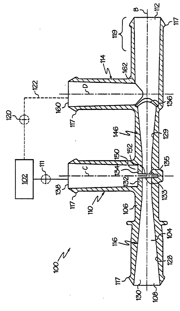
[0026] figure 1 and 2 Different views of the aspirator 100 are shown. The aspirator 100 may be used in an engine, such as that of a vehicle, to provide vacuum to a device. exist figure 1 The middle aspirator 100 is connected to a device 102 requiring a vacuum, while the aspirator 100 generates a vacuum for said device 102 by means of air flow through a channel 104, which extends approximately along the length of the aspirator and is designed to generate Venturi effect. The aspirator 100 includes a body 106 defining a passage 104, while the body 106 has three or more ports that may be connected...


PUM


Abstract

Aspirators are disclosed herein that include a body defining a Venturi gap between an outlet end of a converging motive section and an inlet end of a diverging discharge section and have a suction port in fluid communication with the Venturi gap. The converging motive section defines a circular-shaped motive inlet and defines an elliptical- or polygonal-shaped motive outlet, and the diverging discharge section defines an elliptical- or polygonal-shaped discharge inlet. In one embodiment, the converging motive section defines an inner passageway that transitions as a hyperbolic function from the circular-shaped motive inlet to the elliptical- or polygonal-shaped motive outlet and the elliptical- or polygonal-shaped motive outlet has an area that is less than the area of the circular-shaped motive inlet.

Description

[0001] related application [0002] This application claims priority to US Provisional Application No. 61 / 833746, filed June 11, 2013. technical field [0003] This application relates to aspirators that use the Venturi effect to create a vacuum, and more particularly to aspirators that achieve a user-selected maximum motive flow rate by increasing the circumference of the internal passages at the motive outlet end and the discharge inlet end. Long with increased suction flow. Background technique [0004] Engines, such as vehicle engines, are downsized and supercharged, which reduces the vacuum available from the engine. The vacuum has many potential uses, including use in vehicle brake boosters. [0005] One solution to insufficient vacuum is to install a vacuum pump. However, vacuum pumps have a high cost and weight penalty for the engine, their power consumption may require additional generator capacity, and their low efficiency may hinder fuel economy improvement mea...

Claims


Application Information

Patent Timeline
Patent Type & Authority Applications(China)
IPC IPC(8): B60T13/52B60T17/04
CPCB01F5/0413B60T13/52B60T17/02Y10T137/87587
Inventor D·E·弗莱彻B·格雷琴K·汉普顿M·吉尔默A·尼德特
Owner DAYCO IP HLDG
Learn More