A tilting wheel type turning device
A technology of tilting wheels and turning wheels, which is applied in transportation and packaging, cable railways, motor vehicles, etc., can solve the problems of heavy maintenance workload, large equipment impact, and large vibration, and achieve small maintenance workload, large turning angle, The effect of small turning radius
- Summary
- Abstract
- Description
- Claims
- Application Information
AI Technical Summary
Problems solved by technology
Method used
Image
Examples
Embodiment 1
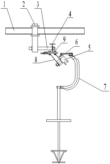
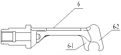
[0019] refer to figure 1 , the present embodiment includes two beams 1, each beam 1 is provided with a hanger 2 below, the hanger 2 is fixed to the beam 1, each hanger 2 is provided with a half shaft 3, and a workmanship is provided between the two half shafts 3. I-beam 4 and I-beam 4 are provided with bottom plate 9, which is fixed by I-beam 4 and half shaft 3; bottom plate 9 is provided with oblique square steel frame 8, and under bottom plate 9 is provided with inclined turning wheel 5, oblique turning The wheel 5 is fixed with the base plate 9 by the inclined square steel frame 8, the inclined turning wheel 5 is at an angle of 30° with the vertical direction, the concave surface of the rim groove of the inclined turning wheel 5 is composed of an arc surface and a plane, the top of the inclined turning wheel 5 Run the wire rope with fixed grip 6, refer to image 3 , the gripping device 6 includes a movable claw 6-1 and a fixed claw 6-2. When the movable claw 6-1 and the fi...
Embodiment 2
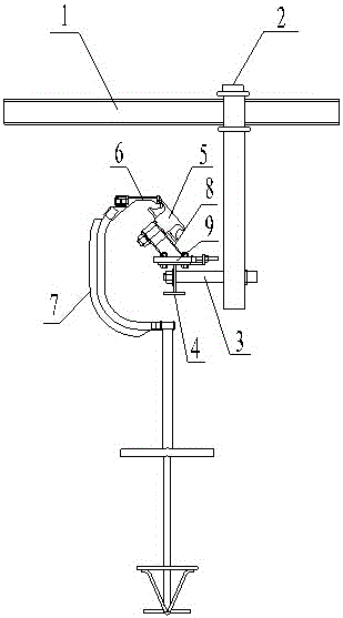
[0021] refer to figure 2 The difference between the present embodiment and embodiment 1 is only that the base plate 9 is located above the I-beam 4, the inclined turning wheel 5 is located above the base plate 9, and the inclined turning wheel 5 forms an angle of 45° with the vertical direction. All the other are with embodiment 1.
Embodiment 3
[0023] refer to Figure 4 , The difference between this embodiment and Embodiment 1 is only that the number of inclined turning wheels 5 is four, and the inclined turning wheels 5 are arranged side by side to form an inclined turning wheel set. All the other are with embodiment 1.
[0024] When the present invention is in use, the wire rope of the cableway is located in the rim groove of the inclined turning wheel 5, and the rope grip 6 can be a movable rope grip or a fixed rope grip, and the rope grip 6 is used to clamp the wire rope, and the wire rope runs along the curve , to drive the oblique turning wheel 5 to run. During the curved operation of the wire rope, the steel wire rope is subject to its own gravity and the tension in the direction of the center of the circle when turning. Direction blocking rope (that is, to balance the tension in the direction of the center of the wire rope).
PUM
 Abstract
Description
Claims
Application Information
 - R&D
- Intellectual Property
- Life Sciences
- Materials
- Tech Scout
- Unparalleled Data Quality
- Higher Quality Content
- 60% Fewer Hallucinations
Browse by: Latest US Patents, China's latest patents, Technical Efficacy Thesaurus, Application Domain, Technology Topic, Popular Technical Reports.
© 2025 PatSnap. All rights reserved.Legal|Privacy policy|Modern Slavery Act Transparency Statement|Sitemap|About US| Contact US: help@patsnap.com


