
A scissor lift walking support mechanism
A support mechanism and lift technology, applied in the direction of lifting frame, lifting device, etc., can solve the problems of lifting different cars, avoiding the breakage and movement of the roller shaft, so as to improve the scope of application, avoid breakage, and be easy to manufacture Effect
- Summary
- Abstract
- Description
- Claims
- Application Information
AI Technical Summary
Problems solved by technology
Method used
Image

Examples
Embodiment Construction
[0016] The present invention will be further described below in conjunction with specific embodiments.
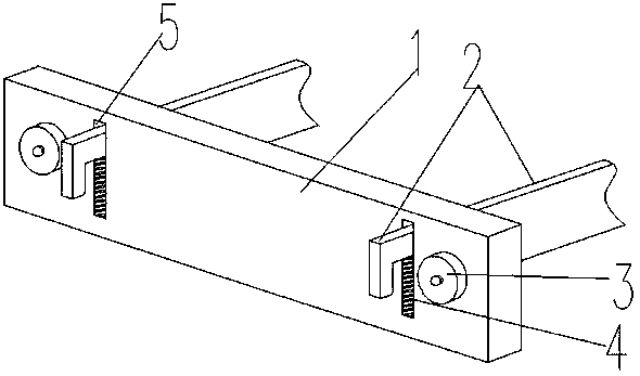
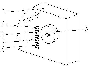
[0017] Such as figure 1 and figure 2 As shown, a scissor lift walking support mechanism includes a vertical plate 1, a hanging plate 2, a roller 3 and an elastic support structure 4, and the two ends of the vertical plate 1 are provided with the same hanging plate groove 5, and the The bottom end of the hanging plate groove 5 is fixed with an elastic support structure 4, and the elastic supporting structure 4 includes a sleeve rod 6, a sleeve 7 and a spring 8, and the sleeve pipe 7 is fixedly connected with the bottom end of the hanging plate groove 5, A sleeve rod 6 is sleeved in the sleeve pipe 7, and the upper end of the sleeve rod 6 is fixedly connected with the lower end of the hanging plate 2. The sleeve rod 6 and the sleeve pipe 7 are all arranged inside the spring 8, and the spring 8. The two ends are respectively fixedly connected with the bottom end of the hang...
PUM
 Abstract
Description
Claims
Application Information