

Pressure blasting laboratory layout design
A layout design, laboratory technology, applied in the direction of measuring devices, industrial buildings, instruments, etc., can solve the problems of main building and personnel injury, insecurity, occupying large indoor space, etc., to improve the economic benefits of enterprises, convenient production and operation, The effect of saving equipment investment
- Summary
- Abstract
- Description
- Claims
- Application Information
AI Technical Summary
Problems solved by technology
Method used
Image

Examples
Embodiment Construction
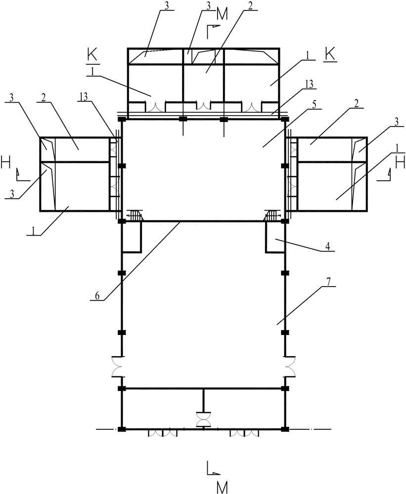
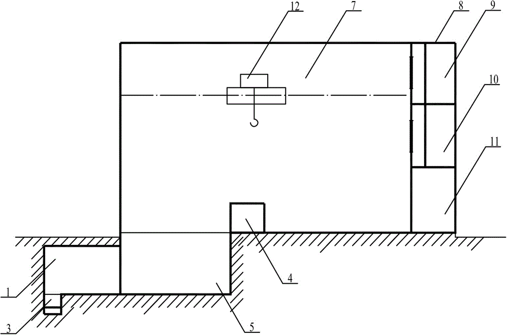
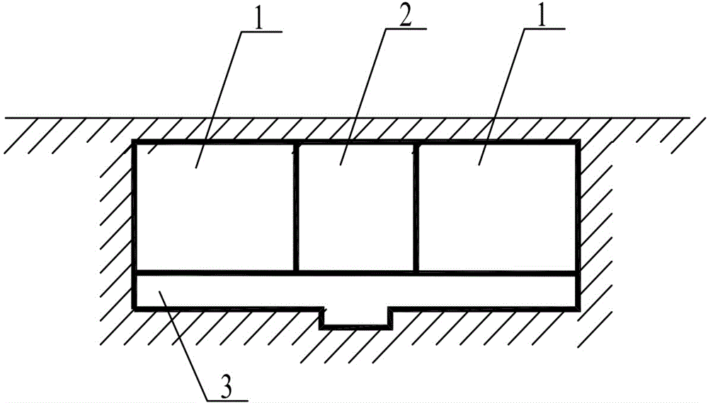
[0018] See attached figure 1 , the present invention includes a preparation area 5 and several hydraulic blasting chambers 1 arranged underground, as well as a control room 4, an object storage area 7 and an office area 8 arranged on the ground, and the hydraulic blasting chamber 1 is provided with an independent or shared pressurized The machine room 2, several hydraulic blasting rooms 1 and the pressurized machine room 2 are respectively set in the shape of "product" outside the preparation area 5 underground of the laboratory; the object storage area 7 is set on the side of the office area 8 on the ground of the laboratory and Facing the preparation area 5; the control room 4 is arranged in the object storage area 7 and faces both sides of the preparation area 5 side; the several hydraulic blasting chambers 1 and the booster room 2 are isolated from the underground structure of the preparation area 5 Seam 13 is disengaged; the hydraulic blasting chamber 1 is formed by pouri...
PUM
 Abstract
Description
Claims
Application Information