Gear transmission shaft device

A gear transmission and shaft device technology, which is applied to transmission parts, hoisting devices, transmission components, etc., can solve the problem of not meeting the requirements of bearing service life and high speed at the same time, the support span of the gear transmission shaft is small, and the bearing life is long It achieves the effect of simple structure, good reliability and economy, and easy manufacturing and assembly without meeting the requirements and other problems.

Inactive Publication Date: 2015-01-28
HUNAN NANFANG AVIATION HIGH ACCURATE DRIVE
View PDF6 Cites 4 Cited by
  • Summary
  • Abstract
  • Description
  • Claims
  • Application Information

AI Technical Summary

Problems solved by technology

Conventional rolling bearing arrangements for supporting gear transmission shafts include: two back-to-back or face-to-face tapered roller bearings are used for support, which cannot meet the requirements of bearing service life and high speed at the same time; the second is to use two face-to-face tapered roller bearings plus a Cylindrical roller bearings take up a lot of space, and the support span of the gear transmission shaft is small, which is not conducive to gear meshing transmission; secondly, the support method of two cylindrical roller bearings plus a four-point contact ball bearing meets the high speed requirements , but the bearing life does not meet the requirements

Method used


Image

  • Gear transmission shaft device
  • Gear transmission shaft device
  • Gear transmission shaft device

Examples


Embodiment Construction

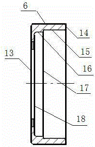
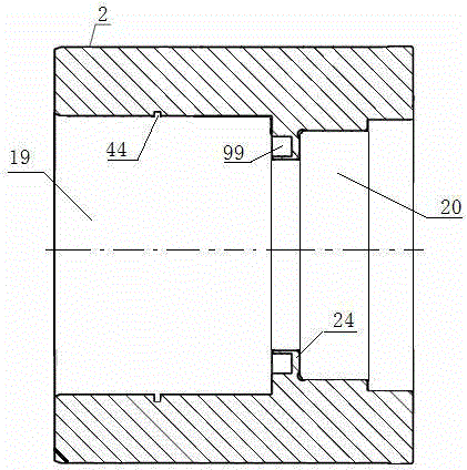
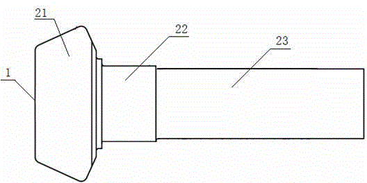
[0019] The gear transmission shaft device of the present invention includes a box body 2 and a gear transmission shaft 1 arranged in the box body 2 . The box body 2 is composed of a first inner cavity 19 and a second inner cavity 20 . The gear transmission shaft 1 is composed of a gear 21 , a large shaft 22 and a small shaft 23 . A cylindrical roller bearing 3 , a tapered roller bearing A7 and a tapered roller bearing B8 are sequentially arranged on the gear transmission shaft 1 . The cylindrical roller bearing 3 is placed between the inner ring 31 of the cylindrical roller bearing and the outer ring 32 of the cylindrical roller bearing. The inner ring 31 of the cylindrical roller bearing is sleeved on the large shaft 22 , and the outer ring 32 of the cylindrical roller bearing is in contact with the inner peripheral surface of the first inner cavity 19 of the box body 2 . The tapered roller bearing A7 is placed between the inner ring 71 of the tapered roller bearing A and t...


PUM


Abstract

The invention relates to a gear transmission shaft device. The gear transmission shaft device comprises a box body and a gear transmission shaft which is arranged in the box body, and is characterized in that the gear transmission shaft consists of a gear, a large shaft and a small shaft, the gear transmission shaft is sequentially provided with a cylindrical roller bearing, a spacing sleeve, a conical roller bearing A, a spacing ring and a conical roller bearing B, which are tightened onto the gear transmission shaft; a convex ring of an inner cavity of the box body is provided with a spring concave cavity for installing a spring and a circumferential annular groove which is provided with a retainer ring. The gear transmission shaft device is simple in structure and easy to manufacture and assemble; by adopting the supporting of the cylindrical roller bearing and two back-to-back conical roller bearings, the gear transmission shaft can bear large radial force and axial force at the high rotation speed, the gear transmission has good engagement characteristics, the transmission efficiency of the gear transmission shaft is improved, the service life of the gear transmission shaft is prolonged, the application and maintenance expense of the gear transmission shaft device is reduced, and the reliability and economical performance are good.

Description

technical field [0001] The invention relates to a transmission shaft device, in particular to a gear transmission shaft device. Background technique [0002] The gear transmission device using rolling bearings requires the rolling bearings to have a long service life, high operating speed, small footprint, and easy installation. It must also bear large axial force and large radial force when running at high speed. Conventional rolling bearing arrangements for supporting gear transmission shafts include: two back-to-back or face-to-face tapered roller bearings are used for support, which cannot meet the requirements of bearing service life and high speed at the same time; the second is to use two face-to-face tapered roller bearings plus a Cylindrical roller bearings take up a lot of space, and the support span of the gear transmission shaft is small, which is not conducive to gear meshing transmission; secondly, the support method of two cylindrical roller bearings plus a fo...

Claims


Application Information

Patent Timeline
Patent Type & Authority Applications(China)
IPC IPC(8): F16H55/02F16H57/021
CPCF16H55/02F16H57/021F16H2700/00
Inventor 葛玉柱雷雪梅杨子文
Owner HUNAN NANFANG AVIATION HIGH ACCURATE DRIVE
Why Eureka
Try Eureka