Energy-saving atmosphere box-type furnace

An atmosphere box and furnace body technology, which is applied in the field of heat treatment equipment, can solve the problems of high specific heat capacity of thermal insulation bricks, dead ends of powder heat treatment, and effectiveness, and achieve the effect of low specific heat capacity and uniform heat distribution.

Inactive Publication Date: 2015-01-28
浙江宇辰工业炉有限公司
View PDF10 Cites 7 Cited by
  • Summary
  • Abstract
  • Description
  • Claims
  • Application Information

AI Technical Summary

Problems solved by technology

However, the disadvantages of this atmosphere box-type furnace are: on the one hand, the heating elements are all arranged on the inner wall surface of the holding furnace body 1, and the heat transfer inside the holding furnace body is not uniform and effective; on the other hand, the holding furnace body The insulation furnace lining made of insulation bricks is not high in insulation and the specific heat capacity of insulation bricks is high, that is, the energy consumption is serious
[0003] In addition, due to the high temperature of the protective gas in the holding furnace body, it has a tendency to float upwards and there is no return air channel to limit its flow direction, so the flow direction of the protective gas is not limited, and the kinetic energy brought to the protective gas by driving the fan blades cannot be used. The shielding gas flows into every area of ​​the holding furnace body, that is, there are problems of dead angle and uneven hardenability for the heat treatment of the powder; moreover, the existing atmosphere box furnace can only control the flow rate of the internal shielding gas by driving the speed of the fan blades , but the flow rate of the protective gas for heat treatment of the powder through the furnace body can not be controlled

Method used


Image

  • Energy-saving atmosphere box-type furnace
  • Energy-saving atmosphere box-type furnace
  • Energy-saving atmosphere box-type furnace

Examples


Embodiment Construction

[0019] The preferred embodiments of the present invention will be described in further detail below in conjunction with the accompanying drawings.

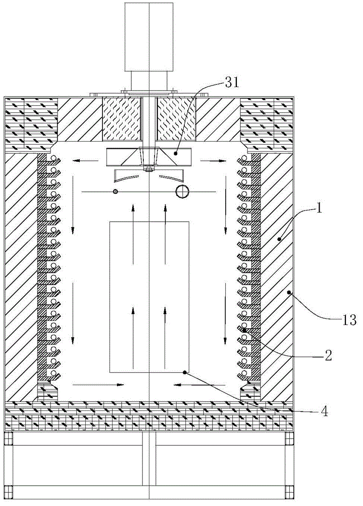
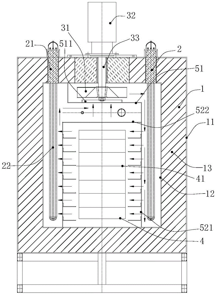
[0020] Such as Figure 2~Figure 5 The shown energy-saving atmosphere box furnace includes a holding furnace body 1 into which a protective gas is passed, a heating device for heating the protective gas, and a driving device for driving the flow of the protective gas, and for placing A powder furnace inner bladder 4, and a return air channel for guiding the protective gas.

[0021] The holding furnace body 1 includes an outer furnace wall 11 and an inner furnace wall 12, and a holding furnace lining 13 made of ceramic aluminum silicate. The holding furnace lining 13 is filled between the outer furnace wall 11 and the inner furnace wall 12; the ceramic aluminum silicate has It has the characteristics of fire resistance, heat preservation and heat insulation, and its specific heat capacity is lower than that of traditional insulation bri...


PUM


Abstract

The invention relates to the field of thermal treatment equipment and discloses an energy-saving atmosphere box-type furnace. The energy-saving atmosphere box-type furnace comprises a heat preservation furnace body which is filled with protection gas, a heating device for heating the protection gas, a driving blade used for driving the protection gas to flow and a furnace body inner container used for storing to-be-processed powder, wherein the driving blade, the furnace body inner container and the heating device are arranged in the heat preservation furnace; the driving blade is arranged above the furnace body inner container; the heating device comprises heating elements which are arranged on two sides of the furnace body inner container; each heating element comprises a clamping base and a plurality of U-shaped heating tubes with free ends arranged in the clamping base; the clamping bases are hermetically arranged on the heat preservation furnace body in a penetrating mode; the plurality of U-shaped heating tubes are arranged inside the heat preservation furnace body and are staggered with each other; the heat preservation furnace body comprises an outer furnace wall, an inner furnace wall and a heat preservation furnace lining; the heat preservation furnace lining is made of aluminum silicate ceramic and is filled between the outer furnace wall and the inner furnace wall. The atmosphere box-type furnace is low in energy consumption and uniform in heat transfer.

Description

Technical field [0001] The invention relates to the field of heat treatment equipment, in particular to an energy-saving atmosphere box furnace. Background technique [0002] The atmosphere box furnace is a protection furnace that prevents oxidation and decarburization when the powder to be processed is subjected to high temperature heating treatment. Such as figure 1 The existing atmosphere box furnace shown includes a heat preservation furnace body 1. The heat preservation furnace lining 13 in the heat preservation furnace body 1 is composed of piles of heat preservation bricks, and the inner wall surface of the heat preservation furnace body 1 is provided with a plurality of heating elements 2 and the heat preservation furnace body There is a driving fan 31 on the upper part of the inside and a furnace inner bladder 4 below the driving fan 31; when in use, the powder to be processed is placed on the furnace inner bladder, and the heating element heats the protective gas in the...

Claims


Application Information

Patent Timeline
Patent Type & Authority Applications(China)
IPC IPC(8): F27B5/04F27B5/14F27B5/16F27B5/06
Inventor 刘世华刘宇博
Owner 浙江宇辰工业炉有限公司
Why Eureka
Try Eureka