Float gauge with vernier or buoy display

A liquid level gauge and float type technology, applied in the field of liquid level measurement, can solve the problems of complex structure of magnetic coupling or vernier or buoy, affecting accuracy and sensitivity, and large friction coefficient, so as to achieve eye-catching and intuitive display, improve accuracy and reduce The effect of friction

Inactive Publication Date: 2018-06-15
DALIAN CONSERVATION SCI & TECH CO LTD
View PDF11 Cites 0 Cited by
  • Summary
  • Abstract
  • Description
  • Claims
  • Application Information

AI Technical Summary

Problems solved by technology

But it has the following disadvantages: both the float and the vernier are sliding friction, resulting in a large friction coefficient, which makes the friction force large and affects the accuracy and sensitivity, and is even unusable
Therefore, the inventor has adopted this structure in the above three patents, but the structure of the magnetic coupling or the vernier or the buoy is still complicated.

Method used


Image

  • Float gauge with vernier or buoy display
  • Float gauge with vernier or buoy display
  • Float gauge with vernier or buoy display

Examples


Embodiment 1

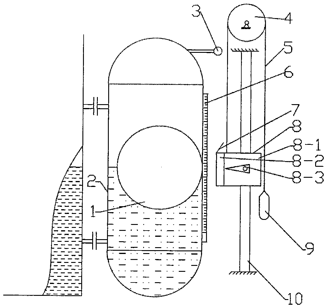
[0075] Such as figure 1 The float type liquid level gauge shown includes a float chamber 2 made of non-ferromagnetic material, a spherical float 1 made of ferromagnetic material, and a cursor 8 outside the float chamber;

[0076] It is characterized by:

[0077] The vernier 8 includes a magnetic steel 8-2 and a linear bearing 8-1, the magnetic steel 8-2 is fixed on the linear bearing 8-1, and the outside of the float chamber 2 is adjacent to the axis parallel to the float chamber Fix a linear guide rail 10, the linear bearing 8-1 is worn on the linear guide rail 10, the magnetic steel 8-2 is located between the linear bearing 8-1 and the float chamber 2, its magnetic pole is facing the float 1, the linear bearing 8 -1 is closely attached to the linear guide rail 10 through the magnetic coupling force between the magnetic steel 8-2 and the float 1.

[0078] In order to indicate clearly and accurately, it is characterized in that an eye-catching pointer 8-3 is fixed outside th...

Embodiment 2

[0081] still as figure 1 As shown, for example, in the case of high temperature and high pressure or high pressure and low density medium, because the wall thickness of the float 1 is relatively thick, the specific gravity of the float 1 is greater than the specific gravity of the measured medium. In order to balance the gravity of the float 1, an upward lifting force is given to the float 1 , On the basis of the above-mentioned scheme, fixed pulley 4 and counterweight 9 and connecting rope or connecting belt 5 have been added. The fixed pulley 4 is fixed above the outer side of the float chamber 2, the connecting rope or belt 5 bypasses the fixed pulley 4, and the two ends are respectively connected with the counterweight 9 and the vernier 8.

[0082] Under normal circumstances, the weight of the counterweight 9 is greater than that of the vernier 8 so that the float 1 and the vernier 8 always form a tension between the upper and lower sides, so as to avoid the formation of a...

Embodiment 3

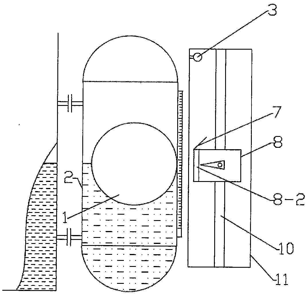
[0084] Such as figure 2 As shown, in order to prevent dust and water, a transparent cursor chamber 11 made of non-ferromagnetic material is adjacent to the float chamber 2, and the cursor 8, the linear guide rail 10 and the laser lamp 3 are fixed in the cursor chamber 11, and the cursor 8 The reflective plate 7 is also fixed on it. The cursor chamber 11 is airtight.


PUM


Abstract

The invention relates to a float-type liquidometer with a vernier or a float for displaying. The float-type liquidometer comprises a float chamber made of nonferromagnetic material, a ball float made of ferromagnetic material and the vernier outside the float chamber. The vernier comprises a magnetic steel and a linear bearing. The magnetic steel is fixed on the linear bearing penetrating a linear guide rail. The other kind vernier comprises a magnetic steel, more than three universal bearings and a plate. The three universal bearings are fixed on the plate in the triangle form. The vernier moves vertically through magnetic bonding force of the magnetic steel and the float. By employing a fixed pulley, a counter weight and a connecting rope, or fixing a buoy on the vernier, the float is lifted upward under the buoyancy of liquid in a vernier chamber. Teletransmission is realized by measuring resistance value of a loop twisted with a resistance wire. By the use of the float-type liquidometer, the problems of on-site indication difficulty and liquid level measurement difficulty of many places are solved. The float-type liquidometer is sensitive, reliable, simple in structure, easy to produce, assemble, adjust and mount, low in cost, marked and visual in displaying and wide in range of application.

Description

technical field [0001] The invention relates to the field of liquid level measurement, in particular to a float type liquid level gauge displayed by a vernier or a buoy. Background technique [0002] Existing on-site indicating liquid level gauges include glass plate type, magnetic flap (column) type, buoy type, two-color water level gauge, etc. The glass plate type can only be visually inspected at close range, and it is difficult to visually inspect after being covered with dust or medium pollution, and the pressure resistance is limited. The structure of the magnetic flap (column) is relatively complex and prone to garbled characters, and the operating temperature is limited. The applicable medium range of the two-color water level gauge is narrow and the pressure resistance is also limited. In addition, the glass plate type liquid level gauge, the magnetic flap (column) type and the two-color water level gauge cannot adopt overall insulation, resulting in high energy c...

Claims


Application Information

Patent Timeline
Patent Type & Authority Patents(China)
IPC IPC(8): G01F23/72
Inventor 王嘉贤李本峰章洪恩梁有祥侯宪华王晓日
Owner DALIAN CONSERVATION SCI & TECH CO LTD
Why Eureka
Try Eureka