
Photoelectric composite rotary connector

A rotary connector and photoelectric composite technology, which is applied in the coupling of optical waveguide, light guide, optics, etc., can solve the problems of different axes, rotary hysteresis of rotary connector, large axial size of photoelectric composite rotary connector, etc., and achieve easy Production and coaxiality are easy to guarantee

Active Publication Date: 2015-01-28
CHINA AVIATION OPTICAL-ELECTRICAL TECH CO LTD
View PDF5 Cites 3 Cited by
  • Summary
  • Abstract
  • Description
  • Claims
  • Application Information

AI Technical Summary

Problems solved by technology

In use, the rotor of the optical rotary connector and the rotor of the electrical rotary connector rotate together to realize the simultaneous transmission of optical and electrical signals in the rotating working mode. The problem with the existing photoelectric composite rotary connector is that it needs to be connected by screws Ensure the coaxiality of the stator of the electric rotary connector and the stator of the optical rotary connector, and then ensure the coaxiality of the rotor of the electrical rotary connector and the rotor of the optical rotary connector. Accumulated errors, the optical rotary connector and the electric rotary connector are prone to misalignment, which may easily cause the rotation delay of the rotary connector, the large change in the insertion loss of the optical rotary connector, and the large change in the contact resistance of the electric rotary connector; in addition The axial dimension overlap between the optical rotary connector and the electrical rotary connector is less, resulting in a larger axial dimension of the optoelectronic composite rotary connector

Method used


Image

  • Photoelectric composite rotary connector

Examples


Embodiment Construction

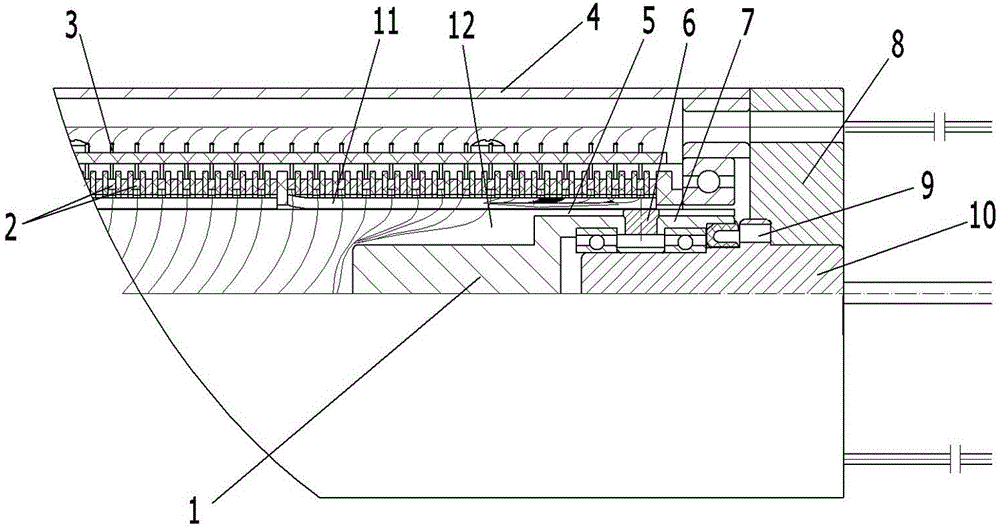
[0013] Examples of optoelectronic composite rotary connectors are figure 1 As shown: it includes an optical rotary connector and an electrical rotary connector. The optical rotary connector includes an optical rotary connector stator 10 and an optical rotary connector rotor 1 that are rotatably assembled with coaxial axes. The optical rotary connector stator 10 and the optical rotary connector are connected The rotor 1 is arranged front and back, and the electric rotary connector includes an electric rotary connector stator and an electric rotary connector rotor assembled together on a coaxial line. The cover 8, the rotor of the electric rotary connector includes a rotating shaft 11 whose axis extends in the front-to-back direction, and a plurality of conductive rings 2 are arranged at intervals along the axial direction on the rotating shaft, and a conductive ring 2 is arranged on the stator of the electric rotary connector to be in contact with the conductive ring. In the br...


PUM


Abstract

The invention relates to a photoelectric composite rotary connector comprising an optical rotary connector and an electric rotary connector. An electric rotary connector rotor of the electric rotary connector includes a rotating shaft with the axis extending along the front-back direction. The optical rotary connector consists of an optical rotary connector stator and an optical rotary connector rotor, wherein the stator and the rotor are assembled together in a rotating mode by sharing the same axis. A routing hole is formed in the rotating shaft, wherein the routing hole and the rotating shaft shares the same axis. The optical rotary connector rotor has an axial assembling segment; and the axial assembling segment is fixedly assembled in the routing hole in a matched mode, so that the optical rotary connector rotor and the rotating shaft share the same axis. The optical rotary connector stator and the electric rotary connector rotor of the electric rotary connector are fixedly connected. According to the photoelectric composite rotary connector, coaxiality of the optical rotary connector and the electric rotary connector can be guaranteed easily.

Description

technical field [0001] The invention relates to a photoelectric composite rotary connector for signal transmission. Background technique [0002] The existing photoelectric composite rotary connector includes an electric rotary connector and an optical rotary connector. The electric rotary connector includes an electric rotary connector stator and an electric rotary connector rotor coaxially rotated and assembled on the electric rotary connector stator. The electric rotary connector The rotor of the device includes a rotating shaft whose axis extends along the front-to-back direction. The rotating shaft has a wiring hole whose axis extends along the front-to-back direction. A conductive ring is arranged on the rotating shaft, and a conductive brush that is conductively slidably matched with the conductive ring is arranged on the stator of the electric rotary connector; Connect the optical rotary connector stator and the optical rotary connector rotor assembled together by co...

Claims


Application Information

Patent Timeline
Patent Type & Authority Applications(China)
IPC IPC(8): G02B6/42
CPCG02B6/4219G02B6/4233
Inventor 刘鹏飞
Owner CHINA AVIATION OPTICAL-ELECTRICAL TECH CO LTD
Learn More