Numerical-control automatic boring machine tool for shaft coupler hole

A boring coupling and automatic technology, which is applied in the field of CNC automatic boring coupling hole machine tools, can solve the problem of not being able to meet the hole size tolerance, smoothness and coaxiality consistency, not being able to realize automatic boring, automatic alignment, and not being able to meet the requirements of power plants. Run power generation and other issues on schedule to achieve the effect of convenient reading, high positioning accuracy and high work efficiency

Active Publication Date: 2018-03-27
河北国源电气股份有限公司
View PDF6 Cites 1 Cited by
  • Summary
  • Abstract
  • Description
  • Claims
  • Application Information

AI Technical Summary

Problems solved by technology

However, there are several shortcomings in the above-mentioned prior art: (1) functions such as automatic boring, automatic alignment, and rapid measurement after hole repairing cannot be realized; , Consistency of smoothness and coaxiality: (3) It cannot completely cover the needs of coupling holes with different diameters and different lengths; (4) The machining accuracy is low, no matter whether the holes are ground by manual electric drills or bored by fixing other holes , the coaxiality of the hole cannot be controlled within 0.05: (5) The above-mentioned processes cannot meet the requirements of the coaxiality of the high-voltage rotor shaft, low-pressure rotor shaft, and generator rotor shaft after the coupling is connected due to the above-mentioned problems, which cannot meet the requirements of the power plant. Run power generation on schedule

Method used


Image

  • Numerical-control automatic boring machine tool for shaft coupler hole
  • Numerical-control automatic boring machine tool for shaft coupler hole
  • Numerical-control automatic boring machine tool for shaft coupler hole

Examples


Embodiment Construction

[0031] The present invention will be further described in detail below in conjunction with the accompanying drawings and specific embodiments.

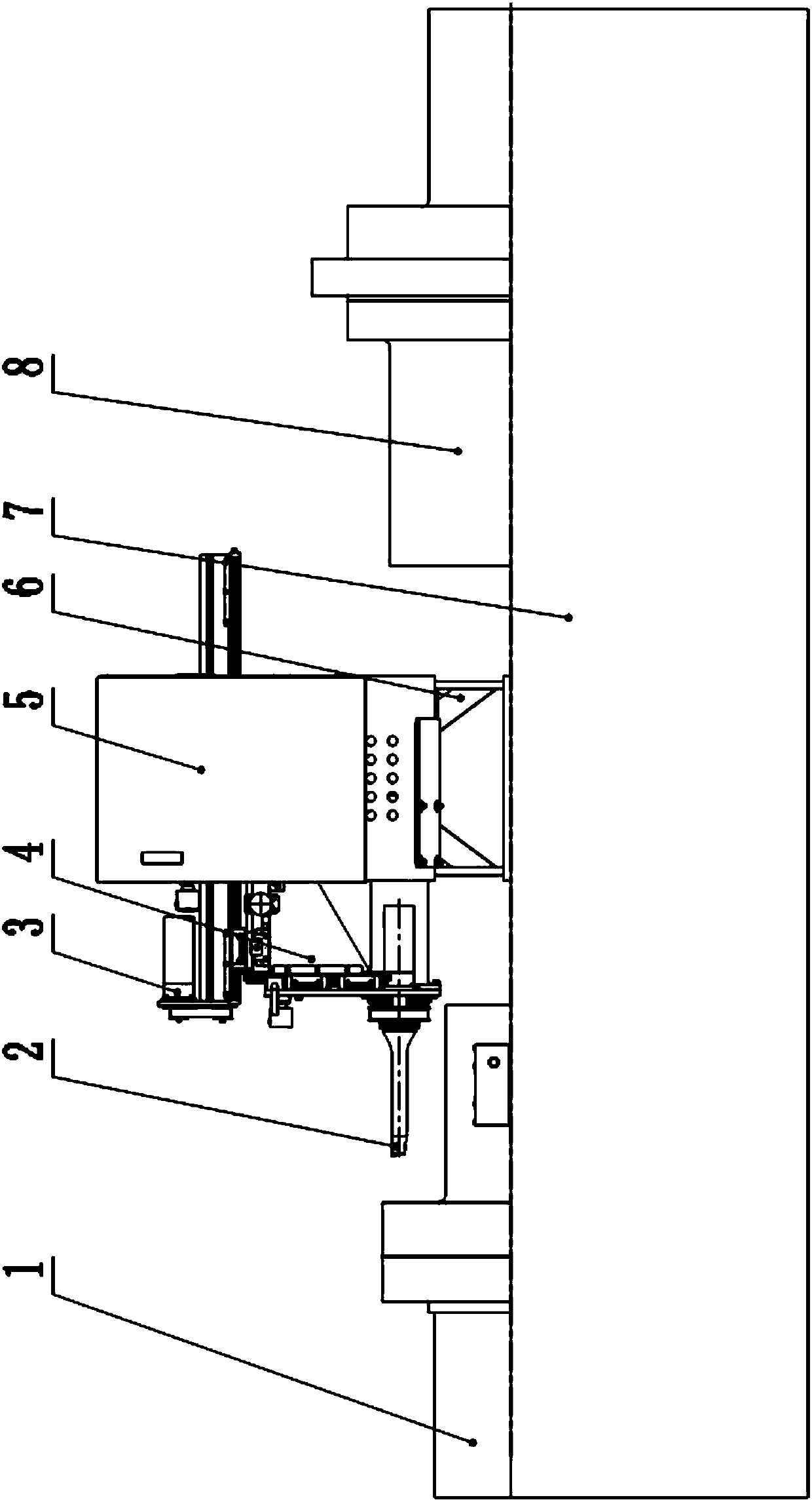
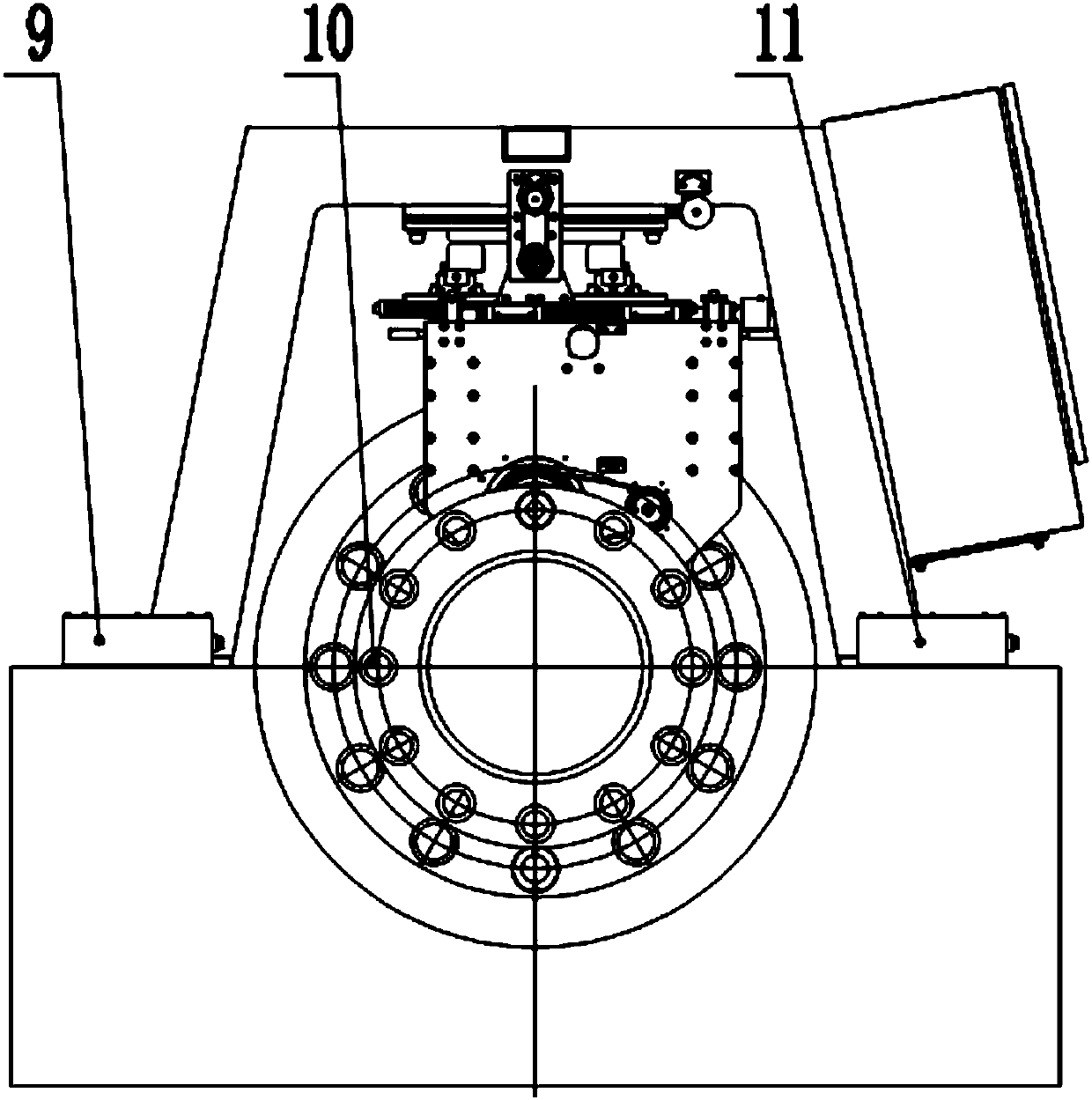
[0032] Such as Figure 1-2 As shown, the present invention discloses a numerical control automatic boring coupling hole machine tool, which includes a frame 6 fixed on a cylinder block 7 of a steam turbine, on which a rotary assembly 2, a feed assembly 3, an adjusting Control part 4, electric control box 5, laser alignment instrument 9 and control touch screen 11; described rotary assembly 2, feed assembly 3, adjustment control part 4, laser alignment instrument 9 and control touch screen 11 are all connected with electric control The box 5 is connected; the rotary assembly 2 is used to realize the forward rotation or reverse rotation of the boring head for boring the bolt hole of the coupling, and the feed assembly 3 realizes that the rotary assembly 2 including the boring head advances and retreats toward the coupling, The laser al...


PUM


Abstract

The invention discloses a numerical-control automatic boring machine tool for a shaft coupler hole. The numerical-control automatic boring machine tool comprises a rack which is fixedly arranged on asteam turbine cylinder body, wherein a rotary assembly, a feeding assembly, a regulating control part, an electric control box, a laser centering apparatus and a control touch screen are arranged on the rack; the rotary assembly, the feeding assembly, the regulating control part, the laser centering apparatus and the touch control screen are connected with the electric control box; the rotary assembly is used for realizing positive rotation or negative rotation of a boring head for boring a shaft coupler bolt hole; the feeding assembly realizes enabling the rotary assembly including the boringhead to advance and retreat towards a shaft coupler; the laser centering apparatus is used for measuring a coaxiality value of the shaft coupler bolt hole and the boring head, feeding back the valueto the electric control box, controlling a corresponding button of the control touch screen according to the fed-back value, and realizing horizontal front-rear movement, vertical up-down movement andhorizontal swing-angle movement of the boring head by automatic linkage of the regulating control part. The numerical-control automatic boring machine tool is used for automatic boring for holes in ashaft coupler of a steam turbine, and can realize functions of automatically centering, automatically feeding and boring, and controlling the action of the touch control screen.

Description

technical field [0001] The invention relates to the technical field of shaft coupling processing, in particular to a numerically controlled machine tool for automatically boring shaft coupling holes. Background technique [0002] The steam turbines in the power plant need to be regularly inspected and rebuilt every year. The key components of the steam turbine high-pressure rotor, low-pressure rotor, and generator rotor are all connected by couplings. The couplings are connected by evenly distributed bolts. Remove the coupling bolts for inspection. Because the bolts are subjected to high temperature, high pressure and torque, the contact surface is damaged, and the coupling holes are generally roughened, elliptical, and damaged. Therefore, before replacing the new bolts, the coupling hole needs to be trimmed, and the outer circle of the bolt should be ground according to the diameter of the trimmed hole. [0003] Due to the limitation of the size and structure of the steam ...

Claims


Application Information

Patent Timeline
Patent Type & Authority Applications(China)
IPC IPC(8): B23B41/00B23B47/00B23B49/00B23Q1/72B23Q5/28B23Q5/34B23Q15/013B23Q17/09
CPCB23B41/00B23B47/00B23B49/00B23Q1/72B23Q5/28B23Q5/34B23Q15/013B23Q17/0952
Inventor 李育江张跃普刘运智揣军伟陈士彬王文冉
Owner 河北国源电气股份有限公司
Why Eureka
Try Eureka