
A method for slow wave welding test of traveling wave tube

A technology of traveling wave tube and slow wave structure, applied in welding equipment, auxiliary welding equipment, welding/cutting auxiliary equipment, etc., can solve problems such as manual assembly instability, save assembly time, reduce welding risk, and improve testing The effect of precision

Active Publication Date: 2020-05-22
INST OF APPLIED ELECTRONICS CHINA ACAD OF ENG PHYSICS
View PDF5 Cites 0 Cited by
  • Summary
  • Abstract
  • Description
  • Claims
  • Application Information

AI Technical Summary

Problems solved by technology

Therefore, an integrated slow-wave welding test fixture is needed to ensure the consistency and reliability of slow-wave parameters, solve the unstable influence of manual assembly caused by separate fixtures, and improve the yield of slow-wave structures

Method used


Image

  • A method for slow wave welding test of traveling wave tube
  • A method for slow wave welding test of traveling wave tube
  • A method for slow wave welding test of traveling wave tube

Examples


Embodiment Construction

[0031] All features disclosed in this specification, or steps in all methods or processes disclosed, may be combined in any manner, except for mutually exclusive features and / or steps.

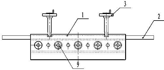
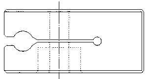
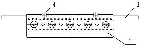
[0032] Such as Figure 1 to Figure 4 As shown, a method for slow-wave welding testing of traveling wave tubes, including: a slow-wave fixture base, which is provided with a cylindrical hole for ensuring the coaxiality of the slow-wave structure, and is equipped with a fastening slow-wave Screws for structural parts; thimbles, used to ensure the parallelism of the end faces of slow-wave structural parts; test dummy windows with waveguide transmission channels, which can be used for cold testing of slow-wave structures after connecting with slow-wave parts; stoppers, used for slow-wave structural parts When the wave structure is welded, the input and output ports are covered; the slow wave structure parts are clamped in the base of the slow wave fixture, and the thimble is used to adjust the pos...


PUM


Abstract

The invention discloses a method used for slow wave welding test of a travelling wave tube. A clamp comprises a clamp base, wherein a through slot is formed in the axial direction of the clamp base; a false window is arranged on the end surface of the clamp base; fastening threaded holes are formed in the side surface of the clamp base; a group of slow wave structural parts used for welding is arranged in the through slot; an input hole and an output hole are formed in each slow wave structural part; each output hole or input hole corresponds to the false window in position; and a baffle block used for blocking each output hole or each input hole is arranged in the false window. The integrated clamp used for slow wave welding test of the travelling wave tube integrates a welding function and a test function, realizes coaxiality requirements of slow wave structural parts during welding, further can complete test on voltage-standing-wave ratio characteristics in case of not dismounting the welding clamp, saves assembly time, improves test precision, reduces risk on welding of slow wave structural parts, and increases the yield of slow wave structures.

Description

technical field [0001] The invention relates to the technical field of microwave electric vacuum devices, in particular to a method for slow-wave welding testing of traveling wave tubes. Background technique [0002] The traveling wave tube is an electric vacuum device that amplifies the input microwave signal. It has the characteristics of high power, wide bandwidth and high gain. It has been widely used in the fields of electronic countermeasures, radar systems and high-speed wireless communications. Folded waveguide traveling wave tube has become one of the micro-electrical vacuum devices with application prospects in the frequency band above 100 GHz due to its high-frequency structure with all-metal structure, fewer competing modes, and large power capacity. Therefore, the terahertz folded waveguide traveling wave tube It has received extensive attention and research, and has shown great application potential in the fields of high-resolution terahertz radar, long-distanc...

Claims


Application Information

Patent Timeline
Patent Type & Authority Patents(China)
IPC IPC(8): B23K37/04G01R27/06
CPCB23K37/0435G01R27/06
Inventor 蒋艺雷文强胡鹏黄银虎宋睿曾造金胡林林马国武孙迪敏卓婷婷陈洪斌
Owner INST OF APPLIED ELECTRONICS CHINA ACAD OF ENG PHYSICS
Learn More