
Self-focusing light path system

An optical path system and self-focusing technology, applied in the microscope field, can solve the problems of time-consuming, short working distance of the objective lens, and slow movement of the electric translation stage.

Active Publication Date: 2015-01-28
MICROFOCUS TECH
View PDF6 Cites 9 Cited by
  • Summary
  • Abstract
  • Description
  • Claims
  • Application Information

AI Technical Summary

Problems solved by technology

[0003] In the past, in the process of auto-focusing by moving the objective lens up and down on the electric translation stage, in order to accurately determine the best clear imaging point, the electric translation stage will move a certain distance S after moving to the best focus point. When using a high-magnification objective lens, the objective lens The working distance is very short, and the objective lens may collide with the detection target when moving the distance S; and because the electric translation stage moves slowly in the whole process, the focusing process takes time, if the translation stage moves fast and It will affect the focusing accuracy and the collision between the objective lens and the detection target

Method used


Image

  • Self-focusing light path system
  • Self-focusing light path system
  • Self-focusing light path system

Examples


Embodiment Construction

[0063] In order to make the above objects, features and advantages of the present invention more comprehensible, the present invention will be further described in detail below in conjunction with the accompanying drawings and specific embodiments.

[0064] The term "one embodiment" or "embodiment" here refers to that specific features, structures or characteristics related to the embodiment can be included in at least one implementation of the present invention. The appearances of "in one embodiment" in various places in this specification do not necessarily all refer to the same embodiment, nor do they necessarily refer to a separate or selected embodiment that is mutually exclusive of other embodiments. Furthermore, the order of blocks in a method, flowchart, or functional block diagram representing one or more embodiments does not necessarily refer to any particular order nor constitute a limitation on the invention.

[0065] see figure 1 , which is a schematic structural...


PUM


Abstract

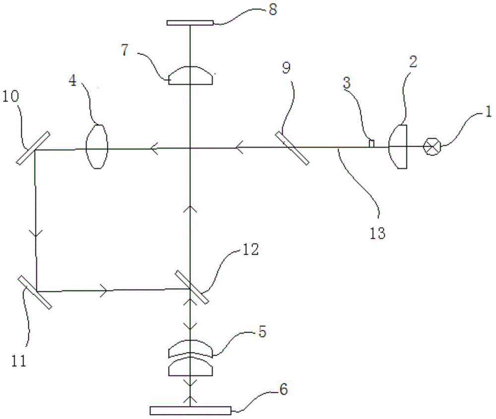
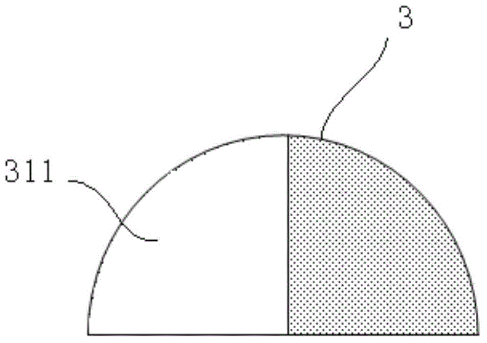
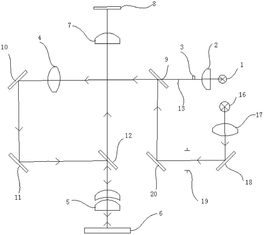
The invention discloses a self-focusing light path system, which comprises a focusing light source, an illuminator, a baffle, a condenser, a first objective lens or a first objective lens assembly, a second objective lens and a camera, wherein the illuminator is located between the focusing light source and the baffle; the baffle is located between the condenser and the illuminator; the focusing light source is located on the focal plane of the illuminator; and the baffle is located on the square focal plane of the illuminator. Compared with the prior art, the self-focusing light path system has the advantages that focusing is accurate, the focusing back stroke distance can be shortened, the focusing time is saved, and collision between the first objective lens or the first objective lens assembly and a detection target can be effectively avoided.

Description

【Technical field】 [0001] The invention relates to the field of microscopes, in particular to a self-focusing optical path system. 【Background technique】 [0002] An optical microscope is composed of a stage, an illumination system, an objective lens, an eyepiece, and a focusing mechanism. The focus controller can be used to drive the focus mechanism to make the objective lens move up and down, so that the observed object can be clearly imaged. [0003] In the past, in the process of auto-focusing by moving the objective lens up and down on the electric translation stage, in order to accurately determine the best clear imaging point, the electric translation stage will move a certain distance S after moving to the best focus point. When using a high-magnification objective lens, the objective lens The working distance is very short, and the objective lens may collide with the detection target when moving the distance S; and because the electric translation stage moves slowly...

Claims


Application Information

Patent Timeline
Patent Type & Authority Applications(China)
IPC IPC(8): G02B21/00
CPCG02B21/244G02B21/245G02B21/248
Inventor 何继中
Owner MICROFOCUS TECH
Learn More