Method for achieving cipher lock, cipher lock formed by the method, and annular lock

A combination lock and password information technology, applied to instruments, time registers, single input port/output port registers, etc., can solve the problems of not being able to use padlocks, low confidentiality, and inoperability, and achieve low cost , simple modification and safe use

Inactive Publication Date: 2015-01-28
马文超
View PDF6 Cites 4 Cited by
  • Summary
  • Abstract
  • Description
  • Claims
  • Application Information

AI Technical Summary

Problems solved by technology

The locks we use now are generally ancient pin locks, which are easy to be unlocked by technology, and the security is not high
The electronic combination locks currently produced are composed of a power supply, keyboard, display, chip, and action mechanism. They are too large to be used for padlocks; locks need to be equipped with a power supply, and they cannot be operated if the power supply fails;

Method used


Image

  • Method for achieving cipher lock, cipher lock formed by the method, and annular lock
  • Method for achieving cipher lock, cipher lock formed by the method, and annular lock

Examples


Embodiment 1

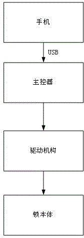
[0041] Such as figure 1 As shown, the present embodiment provides a combination lock based on a computer or a mobile phone, which mainly includes a lock body, a driving mechanism, and a main controller; the main controller is connected with a USB female interface, and the opening of the USB female interface is exposed to the lock. The outside of the main body is convenient for inserting data lines. Through the above settings, when in use, use the data cable to connect the mobile phone and the combination lock through the USB female interface, and the computer or mobile phone will send the password to the main controller in the combination lock. After the comparison is successful, the drive mechanism will be driven by the computer or mobile phone power supply. The driving mechanism drives the dead bolt to move to complete the unlocking.

[0042] Specifically, the main controller includes the following components:

[0043] USB control chip, responsible for the coordination and...

Embodiment 2

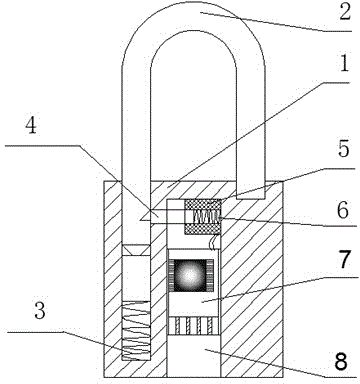
[0053] Such as figure 2As shown, the combination lock based on the mobile phone includes a lock body (1) and a lock ring (2). One end of the lock ring (2) is inserted into the lock body and a first spring (3) is arranged between the two. (1) There is an installation cavity inside, and the installation cavity is provided with a lock tongue (4) at one end for clamping the lock ring (2). The other end of the lock tongue (4) is sleeved with a second spring (6). The second spring (6) is covered with an electromagnet coil (5), the electromagnet coil (5) is connected to the main controller (7), the main controller (7) is connected to a USB female interface (8), and one end of the installation cavity extends to the outside of the lock and form an opening through which the USB female interface (8) is exposed. Through the above settings, the mobile phone is connected to the USB female interface (8) through the data line. After the password is successfully matched, the power supply of ...


PUM


Abstract

The invention discloses a method for achieving a cipher lock, and solves the problems that conventional mechanical locks and cipher locks are inconvenient and expensive. The method is characterized in that a main controller and a driving mechanism are connected together and arranged on a lock; the driving mechanism is used to drive the spring bolt of the lock to move; the user is provided with a mobile controller with a power supply, the cipher information is stored in the mobile controller, and the mobile controller is connected to the main controller through a USB data line to achieve data interaction and power transmission. The method comprises the following steps: (1) the mobile controller and the main controller is connected through a USB data line, and the mobile controller sends cipher information to the main controller through the USB data line; (2) after the main controller receives the cipher information, the main controller judges whether the cipher information is matched or nor, and if the result is positive, the next step is carried out; (3) the mobile controller transmits electrical power to the main controller through the USB data line; (4) the main controller transmits electrical power to the driving mechanism, and the driving mechanism drives the spring bolt of a lock to move so as to unlock the lock.

Description

technical field [0001] The present invention relates to a coded lock, in particular to a method for realizing a coded lock and a coded lock and a circular lock formed thereof. Background technique [0002] In daily life, there are three things we must bring with us when we go out --- mobile phone, keys, and wallet. In particular, forgetting the key is the most troublesome. The locks we use now are generally ancient pin locks, which are easy to be unlocked technically, and the security is not high. The electronic combination locks currently produced are composed of a power supply, keyboard, display, chip, and action mechanism. They are too large to be used for padlocks; locks need to be equipped with a power supply, and they cannot be operated if the power supply fails; Contents of the invention [0003] The purpose of the present invention is to overcome the above-mentioned defects, and provide a method for realizing a password lock which is convenient and low in cost. ...

Claims


Application Information

Patent Timeline
Patent Type & Authority Applications(China)
IPC IPC(8): G07C9/00
Inventor 马文超
Owner 马文超
Why Eureka
Try Eureka