Lifting loading device and material distributing system with same

A technology of equipment and fabric, which is applied in the field of feeding equipment, can solve problems such as deviating from guide rails, running parts deviation, affecting material lifting efficiency and safety, etc., to achieve simple equipment installation, easy installation and maintenance, and reduce equipment failure rate Effect

Pending Publication Date: 2018-12-21
CHANGSHA BROAD HOMES IND FUYANG CO LTD
View PDF1 Cites 2 Cited by
  • Summary
  • Abstract
  • Description
  • Claims
  • Application Information

AI Technical Summary

Problems solved by technology

During the operation of the material lifting device, it is easy for the running parts to deviate or even break away from the guide rail, which affects the efficiency and safety of material lifting

Method used


Image

  • Lifting loading device and material distributing system with same
  • Lifting loading device and material distributing system with same
  • Lifting loading device and material distributing system with same

Examples


Embodiment 1

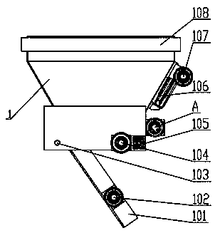
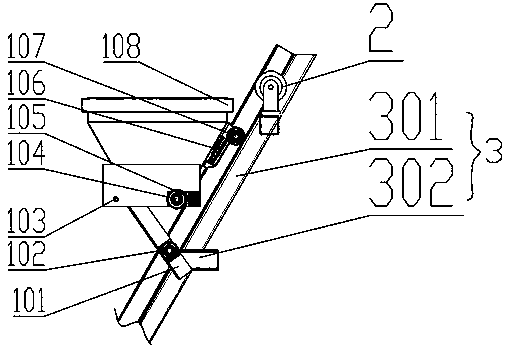
[0040] refer to figure 1 and figure 2 : A kind of lifting feeding equipment of the present embodiment, comprising a lifting bucket 1 and two inclined guide rails 301 for lifting the lifting bucket 1, the lifting bucket 1 includes a hopper body 108 and a discharge door located at the bottom of the hopper body 108 101, the end of the discharge door 101 away from the inclined guide track 301 is rotatably connected to the hopper body 108, and the end close to the inclined guide track 301 is provided with a first walking part 102 supported on the inclined guide track 301, and unloading Material door 101 is positioned between two inclined guide rails 301; Two inclined guide rails 301 are all provided with and communicate with it so that the first walking part 102 enters fork channel 302, and the side of hopper body 108 near inclined guide rail 301 is provided with a The second walking part 107 supported on the inclined guide track 301 is set, and the bottom of the hopper body 108 ...

Embodiment 2

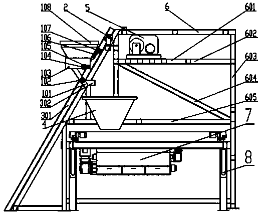
[0054] refer to Figure 3~6 , a distribution system, comprising a distribution rack 8, a distribution device 7, a bracket body 6 and the lifting and feeding device described in Embodiment 1; the inclined guide rail 301 of the lifting and feeding device is obliquely arranged on one side of the bracket body 6 , the driving device 5 is installed on the bracket main body 6;

[0055] Described bracket main body 6 is made up of pillar 603, crossbeam 602, lower platform 605 and upper platform 601, and described crossbeam 602 is installed on the pillar 603, and lower platform 605 and upper platform 601 are erected on crossbeam 602, and described lower platform 605 below A space is reserved for the installation of the cloth rack 8 , and the lower platform 605 of the support body 6 is provided with a receiving hopper 4 , which is located below the side of the fork channel 302 .

[0056] The hopper 4 is a quadrangular pyramid structure with a feed inlet on the top and a discharge outlet...

Embodiment 3

[0058] Compared with Embodiment 2, the cloth system of this embodiment has the following differences:

[0059] refer to Figure 7 , a corridor is provided on the lower platform 605, and ladders 607 connected to the ground and the upper platform 601 are provided on both sides of the corridor. The upper end of the ladder 607 is provided with a protective cage 606 . The ladder 607 is a straight ladder. In order to make it easier for maintenance personnel to go up and down, the ladder 607 can also be designed as an inclined ladder.

[0060] The upper platform 601 and the lower platform 605 of the bracket main body 6 are processed by checkered steel plates or steel gratings, and the pillars 603 and beams 602 are processed by angle steel, H-shaped steel or balance steel.

[0061] Guardrails are provided on the upper platform 601 and the lower platform 605 side parts except the lifting bucket 1 running track side.

[0062] A diagonal brace 604 is provided between the beam 602 and...


PUM


Abstract

The invention provides a lifting loading device. The device comprises a lifting hopper and two inclined guide rails for ascending and descending of the lifting hopper, the lifting hopper comprises a hopper body and a discharging door arranged at the bottom of the hopper body, one end, away from the inclined guide rails, of the discharging door is rotatably connected with the hopper body, one of, close to the inclined guide rails, of the discharging door is provided with first walking parts which are supported on the inclined guide rails, and the discharging door is located between the two inclined guide rails; and the two inclined guide rails are each provided with a fork channel communicating with the corresponding inclined guide rail so as to enable the first walking parts to enter, oneside, close to the inclined guide rails, of the hopper body is provided with one or more sets of second walking parts which are supported on the inclined guide rails, the bottom, close to the inclinedguide rails, of the hopper body is provided with limiting walking parts which are used for controlling the second walking parts not to deviate from the inclined guide rails, and the limiting walkingparts abut against the inclined guide rails. The invention further discloses a material distributing system with the lifting loading device. According to the limiting walking parts arranged at the lifting loading device, the phenomenon that an existing lifting hopper is prone to shifting or derailing when moving along the guide rails is overcome.

Description

technical field [0001] The invention relates to a feeding device for concrete used to produce PC components, in particular to a lifting feeding device for PC component production and a material distribution system with the lifting feeding device. Background technique [0002] At present, in the production process of domestic PC components, the concrete in the mold on the steel trolley is supplied by the distribution machine on the distribution rack (see attached figure 1 cloth machine and cloth frame). The concrete material in the placing machine comes from the mixing station, which is mainly conveyed through the circular feeding frame in the air, and finally unloaded at a fixed point above the placing machine. The equipment investment cost is relatively high, and the feeding equipment is not easy to install and maintain. [0003] CN 201669798U discloses a material lifting device, comprising a hopper and two guide rails inclined to support the hopper; the hopper includes a ...

Claims


Application Information

Patent Timeline
Patent Type & Authority Applications(China)
IPC IPC(8): B28B13/02
CPCB28B13/026
Inventor 张剑陈韶临刘艺罗会文黄超
Owner CHANGSHA BROAD HOMES IND FUYANG CO LTD
Why Eureka
Try Eureka