Punching machine

A stamping machine and stamping mechanism technology, applied in the field of stamping of rigid workpieces, can solve problems such as troublesome operation, low stamping efficiency, and difficult operation, and achieve the effect of convenient operation and improved stamping efficiency

Active Publication Date: 2017-12-19
宁波信基机械科技有限公司
View PDF12 Cites 7 Cited by
  • Summary
  • Abstract
  • Description
  • Claims
  • Application Information

AI Technical Summary

Problems solved by technology

[0004] However, there are still certain problems in the above technical solution: 1. When processing stamping parts of different sizes (such as circular steel sheets with different areas), it is necessary to manual

Method used


Image

  • Punching machine
  • Punching machine

Examples


Embodiment Construction

[0020] The present invention will be described in further detail below by means of specific embodiments:

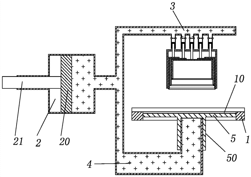
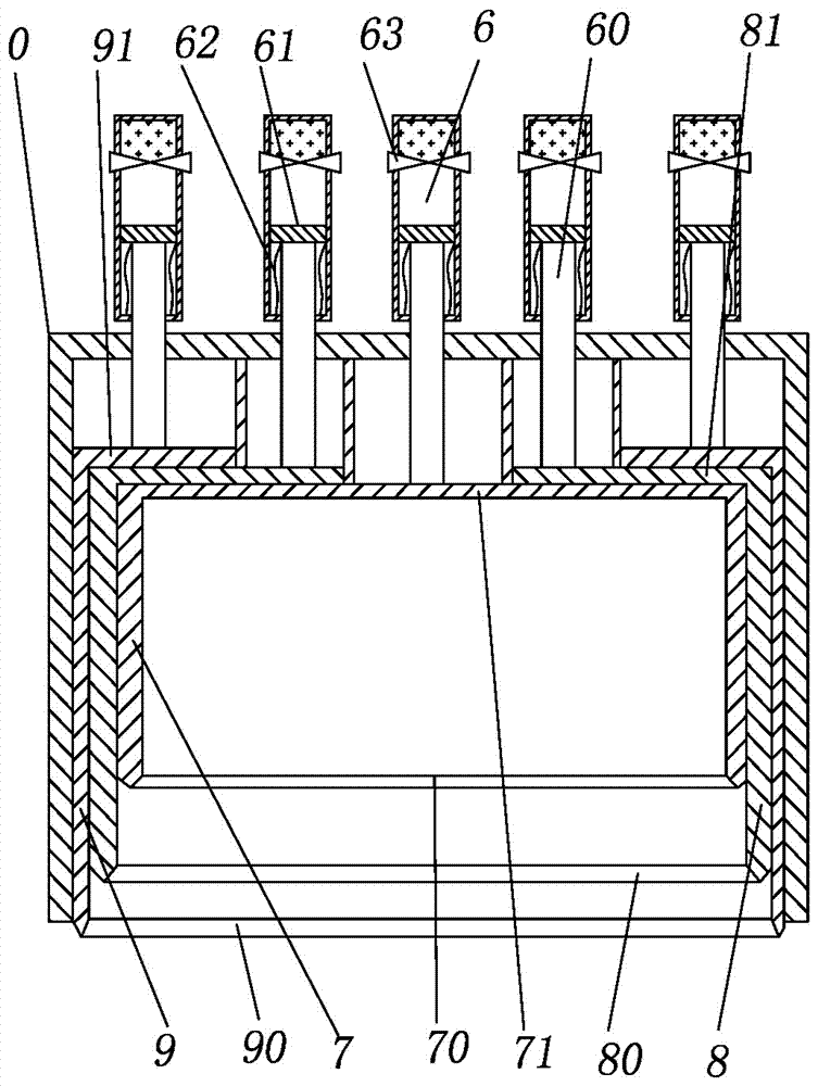
[0021] The reference signs in the drawings of the description include: support plate 1, punching hole 10, oil storage cylinder 2, transverse piston 20, piston rod 21, first branch pipe 3, second branch pipe 4, ejector plate 5, buffer barrel 50, branch Oil pipe 6, connecting rod 60, vertical piston 61, compression spring 62, valve 63, first punching head 7, first punching blade 70, first top plate 71, second punching head 8, second punching blade 80, second The top plate 81 , the third stamping head 9 , the third stamping edge 90 , the third top plate 91 , and the sliding chamber 0 .

[0022] The embodiment is basically as figure 1 As shown: a stamping machine, including a support plate 1, a punching hole 10 is arranged in the support plate 1, and an ejection mechanism, a stamping mechanism, and an oil storage cylinder 2 for storing hydraulic oil; the oil storage cylinder...


PUM


Abstract

The invention relates to the technical field of punching of rigid workpieces, in particular to a punching machine. The punching machine comprises a supporting plate. A punching hole is formed in the supporting plate. The punching machine further comprises an ejector mechanism, punching mechanisms and an oil storage cylinder for storing hydraulic oil. The oil storage cylinder communicates with a first branch pipe and a second branch pipe located below the first branch pipe. The oil storage cylinder is internally and slidably connected with a transverse piston. The transverse piston is connected with a piston rod. The ejector mechanism comprises an ejector plate and a buffer bucket connected with the lower portion of the ejector plate. The number of the punching mechanisms is two. Each punching mechanism comprises a punching head, a connecting rod, a vertical piston and an oil separating pipe. The sizes of the punching heads of all the punching mechanisms are different. According to the technical scheme, the punching machine is characterized in that punching head replacing and punched part picking are very convenient, and the punching efficiency is improved advantageously.

Description

technical field [0001] The invention relates to the technical field of punching of rigid workpieces, in particular to a punching machine. Background technique [0002] Stamping is a forming processing method that applies external force to plates, strips, pipes and profiles by presses and molds to cause plastic deformation or separation to obtain workpieces (stamping parts) of required shape and size. Stamping and forging belong to plastic processing (or pressure processing) and are collectively called forging. The blanks for stamping are mainly hot-rolled and cold-rolled steel sheets and strips. Among the steel products in the world, 60-70% are plates, most of which are stamped into finished products. During the stamping process, traditional stamping machines can only stamp one type and specification of stamping parts, which seriously wastes the efficiency of stamping equipment. [0003] The Chinese patent with the notification number CN206229899U discloses a stamping mac...

Claims


Application Information

Patent Timeline
IPC IPC(8): B30B1/32B30B15/32B30B15/06
CPCB30B1/32B30B15/065B30B15/32
Inventor 王健
Owner 宁波信基机械科技有限公司
Why Eureka
Try Eureka