Clothing treatment equipment
A clothing processing equipment and technology, which is applied to other washing machines, washing machines with containers, textiles, and paper making, etc., can solve the problems of water discharge from rotating barrels, etc., so as to reduce the space occupied by the equipment, the structure of the equipment is simple, and the size of the design can be reduced. Effect
- Summary
- Abstract
- Description
- Claims
- Application Information
AI Technical Summary
Problems solved by technology
Method used
Image
Examples
Embodiment 1
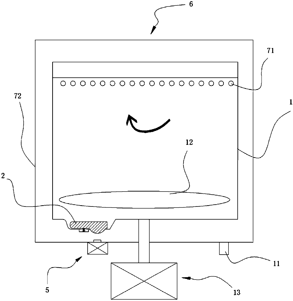
[0084] Such as figure 1 As shown, in the clothes processing equipment described in this embodiment, most of the blocking mechanism 2 is arranged inside the rotary tub 1, and the covering area of the blocking mechanism is larger than the opening area of the drain port, so that the blocking mechanism can be placed on the inside of the drain port. The surroundings are closely fitted with the rotating barrel 1 to ensure the sealing. There may be multiple blocking mechanisms and / or drain outlets, so that the rotary tub can drain water from multiple locations. Through the clothes processing equipment introduced in this embodiment, the inner side of the rotating tub where the blocking mechanism is mainly installed ensures a simple design of the outer side of the rotating tub and avoids collisions with other components outside the rotating tub during rotation. If the clothes processing equipment is a pulsator washing machine, the blocking mechanism is arranged under the pulsator ...
Embodiment 2
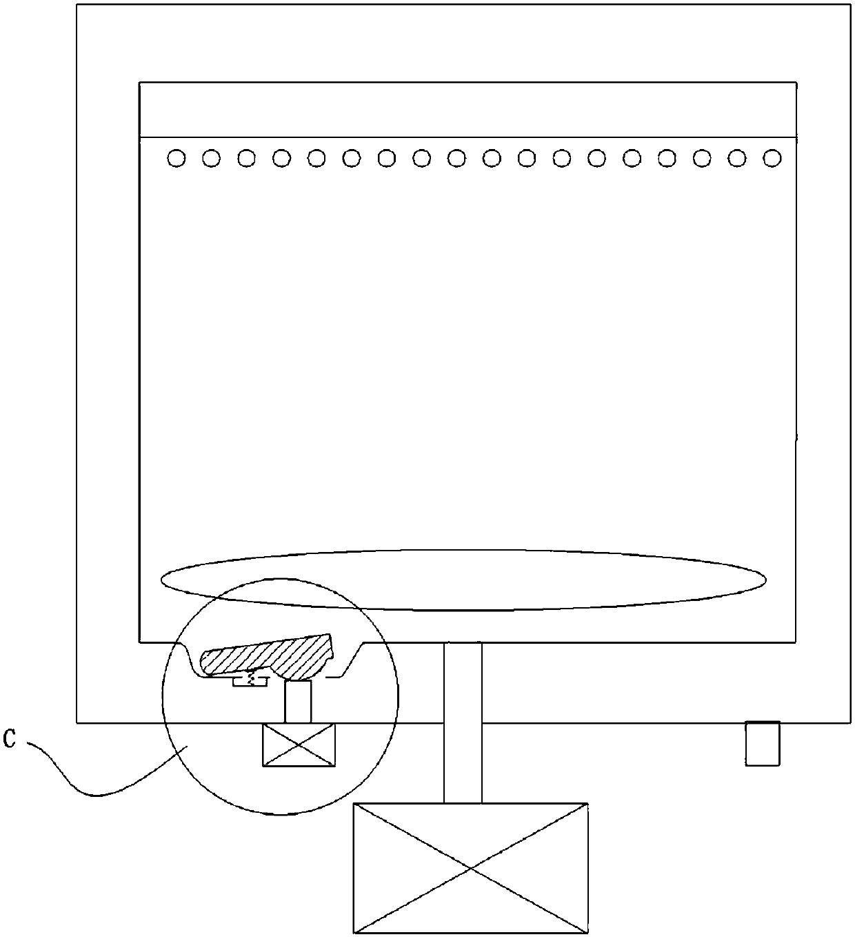
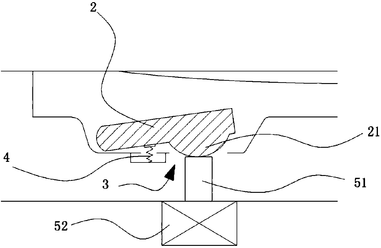
[0088] Such as figure 2 , 3 As shown, the difference between the clothes processing equipment described in this embodiment and the above-mentioned implementation is that the blocking mechanism 2 is reversibly connected to the rotating bucket, so that when the drain port 3 is opened, the right part of the blocking mechanism 2 is shown in the figure. The upward tilt is separated from the rotary barrel, and the left side of the blocking mechanism 2 is kept connected with the rotary barrel. The blocking mechanism 2 in this embodiment is made of elastic materials, such as rubber, silica gel, and the like. The blocking mechanism 2 is a plate-shaped structure, which can maintain the stability of shape when it covers the water outlet 3 . When the blocking mechanism 2 turns over relative to the bottom of the rotating tub, at least a part of the water outlet 3 is opened.
[0089] Furthermore, in the laundry processing device in this embodiment, the rotating tub is connected to one e...
Embodiment 3
[0092] Such as figure 1 , 2 As shown in , 3, the difference between the laundry treatment device described in this embodiment and the above-mentioned implementation is that the laundry treatment device includes an opening mechanism 5 that assists the opening of the sealing mechanism 2, and the opening mechanism 5 is arranged on the rotary tub 1 corresponding to the sealing mechanism 2 Below, the opening mechanism 5 is relatively stationary, and when the rotary bucket 1 rotates, the opening mechanism 5 is also in the casing relative to the equipment (such as Figure 4 The box body 10 shown) is at rest. When the device drains water, the blocking mechanism 2 opens the drain port 3 under the action of the opening mechanism 5 to discharge the water from the rotary bucket 1 .
[0093] Further, in this embodiment, when the device drains water, the ejector rod 51 of the opening mechanism 5 passes through the water outlet 3 and rises to the inside of the rotating bucket, and the bloc...
PUM
 Abstract
Description
Claims
Application Information
 - R&D
- Intellectual Property
- Life Sciences
- Materials
- Tech Scout
- Unparalleled Data Quality
- Higher Quality Content
- 60% Fewer Hallucinations
Browse by: Latest US Patents, China's latest patents, Technical Efficacy Thesaurus, Application Domain, Technology Topic, Popular Technical Reports.
© 2025 PatSnap. All rights reserved.Legal|Privacy policy|Modern Slavery Act Transparency Statement|Sitemap|About US| Contact US: help@patsnap.com


