Locating rod with teeth

A technology of positioning rod and rod body, which is applied to the parts and instruments of the instrument, can solve the problem of time-consuming and labor-intensive pins, and achieve the effect of good positioning effect.

Inactive Publication Date: 2015-01-28
重庆市南川区泰城钢化玻璃制品有限责任公司
View PDF0 Cites 1 Cited by
  • Summary
  • Abstract
  • Description
  • Claims
  • Application Information

AI Technical Summary

Problems solved by technology

[0004] The invention provides a toothed positioning rod to solve the

Method used


Image

  • Locating rod with teeth
  • Locating rod with teeth

Examples


Embodiment Construction

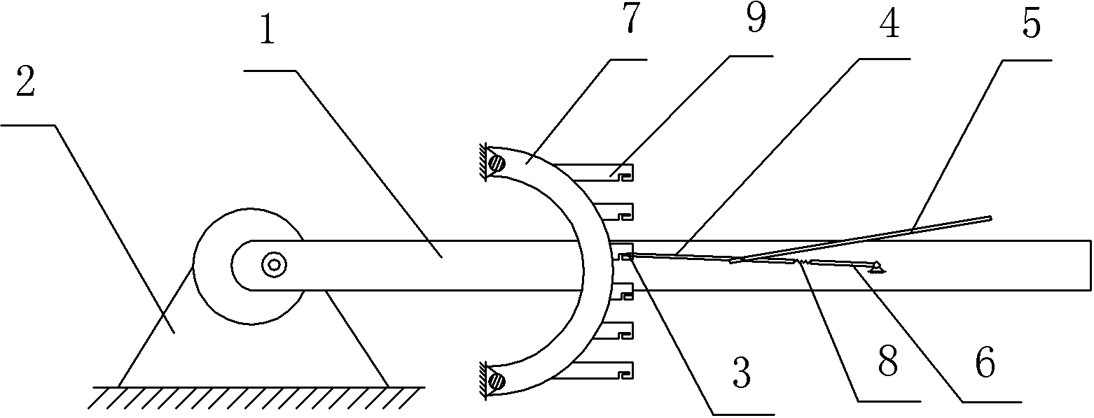
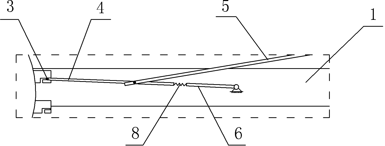
[0015] The reference signs in the drawings of the description include: rod body 1 , frame 2 , bayonet pin 3 , connecting rod 4 , unlocking rod 5 , pole 6 , fixed block 7 , tension spring 8 , and locking teeth 9 .

[0016] Such as figure 1 As shown, a toothed positioning rod in this embodiment includes a rod body 1 and a frame 2, one end of the rod body 1 is hinged on the frame 2, and the other end is a gripping end. It also includes a bayonet pin 3, a connecting rod 4, an unlocking lever 5, a pole 6 fixed on the rod body 1 and a fixed block 7 fixed on the frame 2. On the fixed block 7, there are 6 bayonets 9 distributed along the rotation track of the rod body 1, and an L-shaped bayonet groove matching the size of the bayonet pin 3 is provided on the bayonet 9 corresponding to the tangential direction of the pole body 1 rotation track, and the bayonet pin 3 can be Slide in the card slot. The bayonet pin 3 is coated with a rubber layer, such as figure 2 As shown, bayonet pi...


PUM


Abstract

The invention discloses a locating rod with teeth. The locating rod with the teeth comprises a rod body and a rack. One end of the rod body is hinged to the rack, and the other end of the rod body is a holding end. The locating rod with the teeth further comprises a clamping pin, a connecting rod, an unlocking rod, a supporting rod and a fixing block, wherein the supporting rod is fixed to the rod body, and the fixing block is fixed to the rack. Clamping teeth are distributed on the fixing block along the rotating locus of the rod body. L-shaped clamping grooves matched with the clamping pin in size are formed in the clamping teeth corresponding to the tangential direction of the rotating locus of the rod body. The clamping pin is fixedly connected to the connecting rod. A tension spring is connected between the connecting rod and the supporting rod. One end of the unlocking rod is fixedly connected with the connecting rod, and the other end of the unlocking rod is close to the holding end of the rod body. According to the locating rod with the teeth, people can lock the rod body only by pushing the unlocking rod, compared with the mode of adopting a pin, the locating rod with the teeth is more convenient to use, the L-shaped grooves are adopted, locating in the upper direction, the lower direction and the right direction can be achieved, the tension spring is arranged on the left side to prevent the locating rod from sliding, and the locating effect is good.

Description

Technical field [0001] The invention is a technical field of locking control components. Background technique [0002] The positioning rod refers to the locking rod body. After the rod body is locked, it cannot be moved at will until the exercise can be started until it is unlocked. [0003] The existing positioning rod is locked by inserting the nail, that is, inserting the nail between the rod body and the rack.However, in the method of nails, the nails need to be pulled out and loaded.The nails and the corresponding holes are used to cooperate with the convergence, which is very time -consuming and laborious to pull out and load. Especially when the position is required for multiple times, and the locking position is different.It is very inconvenient to lock the positioning rod. Invention content [0004] The present invention provides a tooth with positioning rod to solve the problem of more time -consuming and labor -intensive punching in locking. [0005] In order to solve...

Claims


Application Information

Patent Timeline
IPC IPC(8): G12B3/02
Inventor 韩国才
Owner 重庆市南川区泰城钢化玻璃制品有限责任公司
Why Eureka
Try Eureka