Box-sharing type ring network cabinet

A technology of ring network cabinet and common box type, which is applied in the direction of substation/switchgear board/panel/desk, switchgear, electrical components, etc., which can solve the cumbersome design of the shell, adjust the degree of gear meshing and the corresponding opening distance. , low production efficiency and other issues, to achieve the effect of simple and convenient assembly process and easy meshing

Active Publication Date: 2015-01-28
PINGGAO GRP +1
View PDF6 Cites 0 Cited by
  • Summary
  • Abstract
  • Description
  • Claims
  • Application Information

AI Technical Summary

Problems solved by technology

The existing problems of this kind of ring main unit are: 1. The components of circuit breaker, load switch and grounding switch have many unit parts, and the degree of integration and modularization is not high. It is difficult to realize the offline pre-assembly of each component. During assembly, each part of the circuit breaker, load switch, and grounding switch must be assembled on the housing separately, resulting in a very slow assembly process of the ring network cabinet and low production efficiency, because it is necessary to install all parts of the components on the housing On the inner wall of the shell, the structure of the shell is also relatively complicated, the design of the shell is cumbersome, and the design cycle of the shell is long; 2. The gear transmission mechanisms of each operating shaft are arranged in the shell, which is not conducive to observing and adjusting the meshing of the gears The degree and the corresponding opening distance also bring difficulties to the assembly to a certain extent.

Method used


Image

  • Box-sharing type ring network cabinet
  • Box-sharing type ring network cabinet
  • Box-sharing type ring network cabinet

Examples


Embodiment Construction

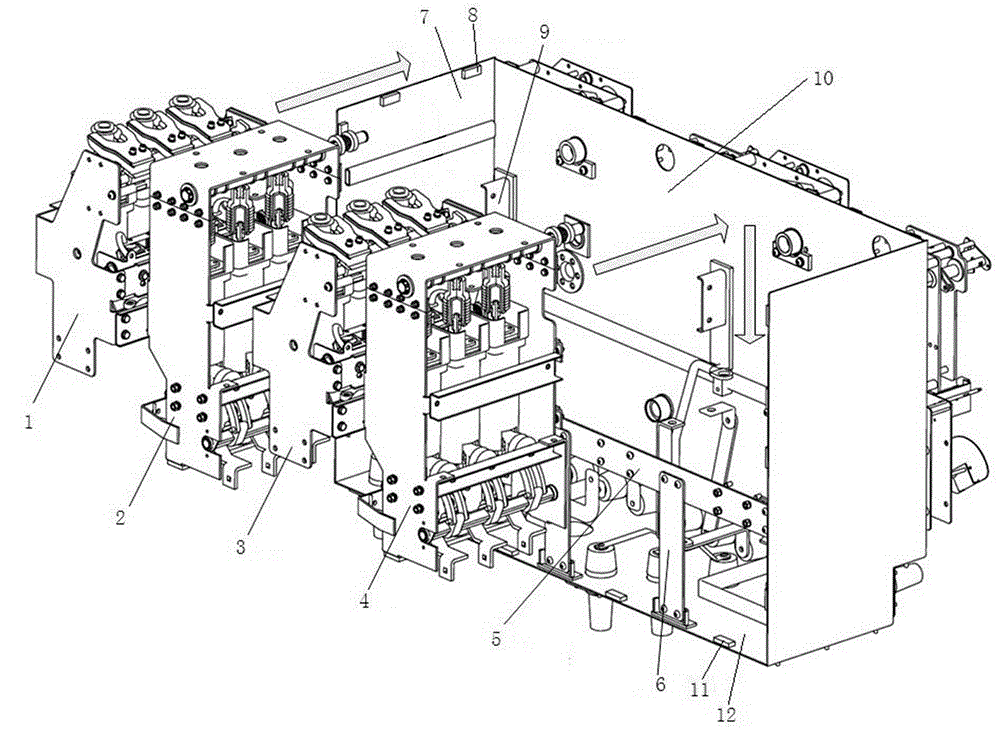
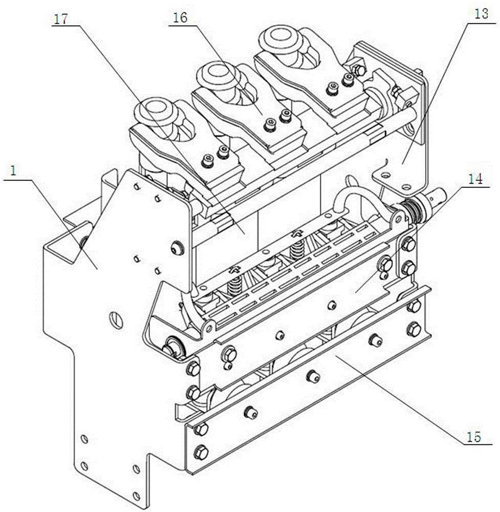
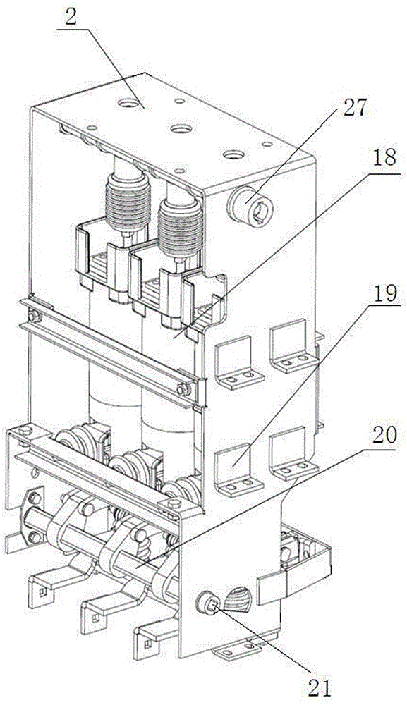
[0018] Examples of common box ring network cabinets Figure 1~4 Shown: includes a shell, the shell includes a top plate, a bottom plate 12 placed between the top plate (not shown in the figure), a front side plate 10 between the bottom plate, a rear side plate (not shown in the figure), a left side plate 7 and On the right side panel, the first mounting frame 1, the second mounting frame 2 and the third mounting frame 3 are arranged at intervals along the left and right directions in the shell, after the first, second, and third mounting frames are pushed into place from back to front Each installation frame is fixed on the housing through a fixed structure, the second installation frame 2 is provided with a circuit breaker and a three-position switch arranged up and down, and the first installation frame 1 is provided with a load switch and a grounding switch arranged up and down, The third installation frame 3 is provided with a load switch fuse combination, which has a load...


PUM


Abstract

The invention relates to a box-sharing type ring network cabinet, and the cabinet comprises a housing, a load switch, and a grounding switch, wherein the load switch and the grounding switch are disposed in the housing. The interior of the housing is provided with a first installation frame. The load switch and the grounding switch are disposed on the first installation frame. The axis of an operating shaft of the load switch and the axis of an operating shaft of the grounding switch respectively extend along a front-back direction. A front side plate of the housing is provided with wall-passing rotating shafts in a sealed rotation manner, wherein the wall-passing rotating shafts are corresponding to the operating shafts in a one-one manner and cross the front and rear sides of the front side plate. The rear ends of the wall-passing rotating shafts are provided with rotation-stopping plugging segments which cooperate with the front ends of the corresponding operating shafts in an opposite-plugging and rotation-stopping manner. The interior of the housing is also provided with a fixing structure which is used for fixing the first installation frame after the first installation frame is pushed towards the front side plate from the back to the front. The cabinet provided by the invention achieves modularized installation, and a gear drive structure can be disposed at a side of the housing.

Description

technical field [0001] The invention relates to switchgear, in particular to a box-common ring network cabinet. Background technique [0002] The ring network cabinet is suitable for the control and protection devices in the power system ring network power supply, terminal power supply or dual radiation power supply system. The common box type ring network cabinet is to set the load switch, circuit breaker, grounding switch, etc. in the same closed shell, and the circuit breaker is not available in every ring network cabinet. Existing box-type ring network cabinets such as the "indoor box-type metal-enclosed ring network cabinet" disclosed in Chinese patent CN201478729U, the ring network cabinet includes a shell and a load switch, a circuit breaker and a grounding switch arranged in the shell , the housing includes a top board, a bottom board, and a front side board, a rear side board, a left side board and a right side board arranged between the top board and the bottom bo...

Claims


Application Information

Patent Timeline
Patent Type & Authority Applications(China)
IPC IPC(8): H02B13/00H02B1/04
CPCH02B1/04H02B13/00
Inventor 费翔潘明袁端磊杨芳祁海洋张永辉杨锐
Owner PINGGAO GRP
Why Eureka
Try Eureka