Footwear outsole member

A technology of components and components, applied in soles, insoles, footwear, etc., can solve problems such as liquid leakage and achieve the effect of mitigating impact force

Inactive Publication Date: 2015-01-28
HIMIKO
View PDF7 Cites 1 Cited by
  • Summary
  • Abstract
  • Description
  • Claims
  • Application Information

AI Technical Summary

Problems solved by technology

[0031] However, even with the above-mentioned measures for preventing liquid leakage, incidents of liquid leakage from the junction between the bottom plate and the cover still occur

Method used


Image

  • Footwear outsole member
  • Footwear outsole member
  • Footwear outsole member

Examples


Embodiment Construction

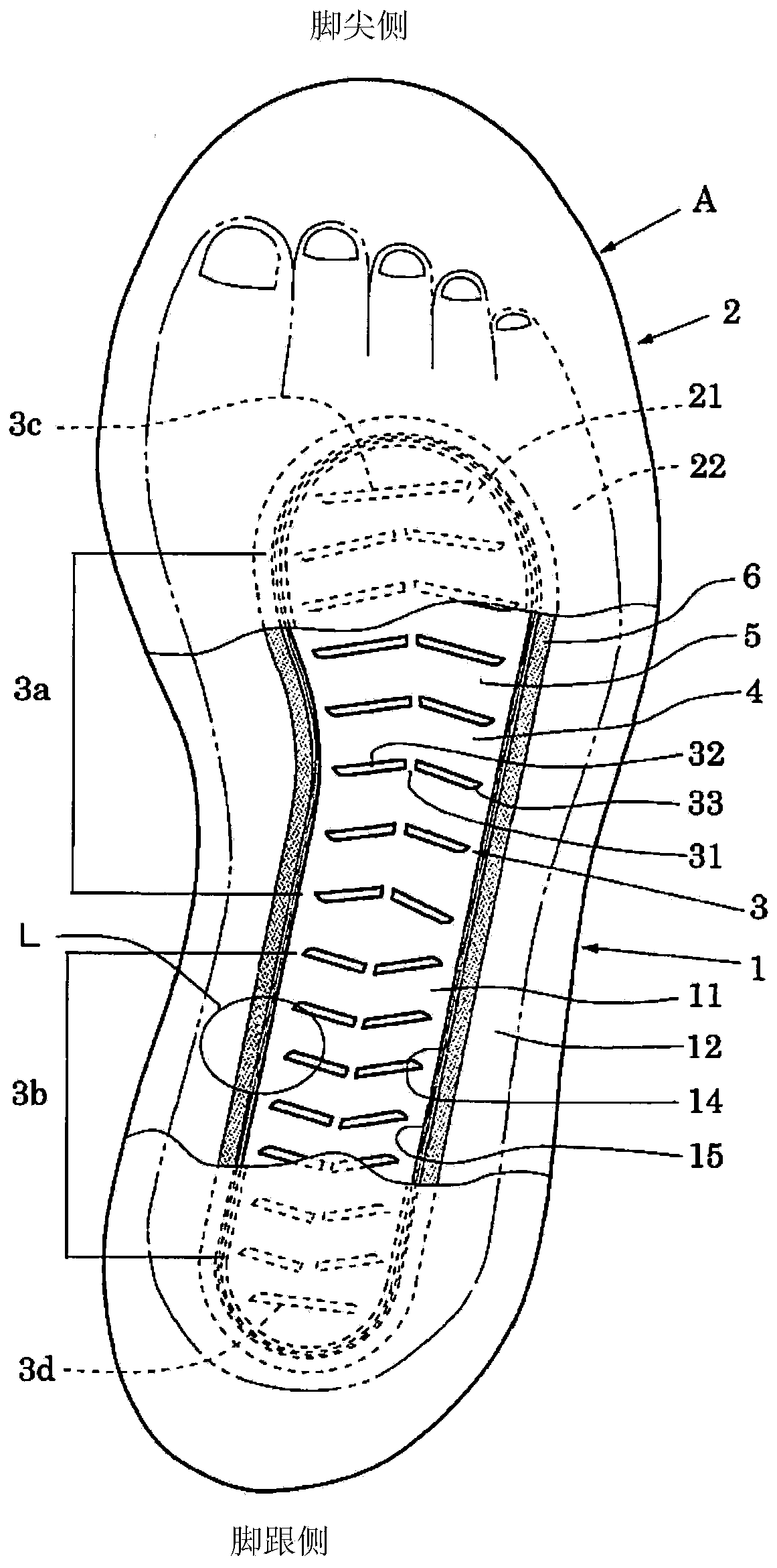
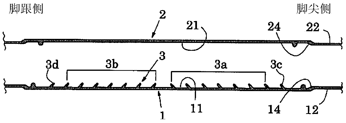
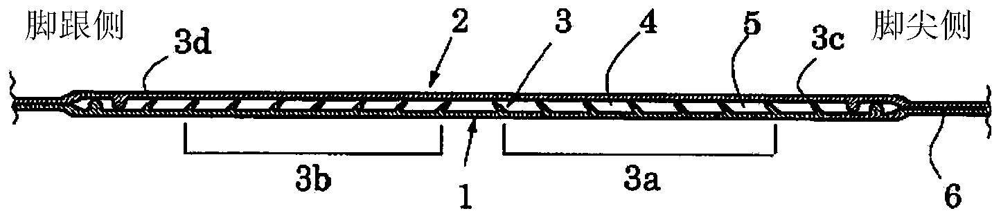
[0084] refer to Figure 1 to Figure 7 , taking the midsole of a shoe as an example to illustrate the bottom member of the shoe of the present invention. Such as figure 1 As shown, the midsole A of the present invention includes a bottom plate 1 , a cover 2 , a plurality of blades 3 and a liquid 4 .

[0085] The bottom plate 1 has a first region 11 having a shape corresponding to the sole of a foot, and a first horizontal flange portion 12 surrounding the entire circumference of the first region. Furthermore, the cover material 2 has a second region 21 facing the first region 11 provided on the bottom plate 1 and a second horizontal flange portion 22 facing the first horizontal flange portion 12 . Additionally, as from figure 1 As can be clearly seen, the first region 11 of the soleplate 1 is formed to have a length from the heel to the front of the root of the toe, and a width in the lateral direction when the sole of the foot is on the ground.

[0086] In addition, if ...


PUM


Abstract

A shoe midsole is configured from a bottom plate (1), a cover (2), a plurality of blades (3), and a liquid (4). The blades (3) are formed so as to rise on a first region (11) provided in the bottom plate (1). The blades (3) are made from a plurality of flat blade elements (32, 33) mutually separated by slits (31) and tilt toward either the toe side or the heel side. The flat blade elements (32, 33) are disposed so as to spread open toward the toe side or the heel side. A sealed space (5) is formed by mutually joining the bottom plate (1) and the cover (2), and the liquid (4) is sealed in the sealed space.

Description

technical field [0001] The present invention relates to a sole member of shoes, and in particular to shoes capable of obtaining a comfortable walking feeling with a sense of stability, absorbing shocks during walking, stimulating soles of the feet to exert a massage effect, and preventing leakage of liquid sealed in the sole member. Bottom member. Background technique [0002] When the heel hits the ground during walking, the impact force on the heel is about 1.25 times the body weight, and, when jogging, it can reach about 3 times the body weight. This impact is transmitted to the heels, ankles, and knees, and further to the waist, and places a burden on these parts. In addition, it is also known that the shock received when the toes are stepped on the ground and lifted is greater than the shock received when the heels are dropped to the ground. [0003] Therefore, the present inventors proposed a midsole capable of dispersing and absorbing the shock received when the sol...

Claims


Application Information

Patent Timeline
Patent Type & Authority Applications(China)
IPC IPC(8): A99Z99/00
CPCA43B13/127A43B7/144A43B13/386A43B7/1445A43B13/189A43B13/40A43B13/181A43B17/026
Inventor 柴田一柴田政男
Owner HIMIKO
Why Eureka
Try Eureka