Antenna circuit and electronic equipment

A technology for antenna circuits and electronic equipment, applied in transducer circuits, electrical components, sensors, etc., can solve the problems of earphone sound quality degradation and interference, and achieve the effect of improving sound quality

Inactive Publication Date: 2015-02-04
XIAOMI INC
View PDF5 Cites 8 Cited by
  • Summary
  • Abstract
  • Description
  • Claims
  • Application Information

AI Technical Summary

Problems solved by technology

[0006] In order to solve the problem in the related art that the ground wire in the earphone is used as the antenna of the FM chip, the antenna signal will interfere with the sound played in the earphone, and the sound quality of the earphone will be degraded. Embodiments of the present disclosure provide an antenna circuit and electronic equipment

Method used


Image

  • Antenna circuit and electronic equipment
  • Antenna circuit and electronic equipment
  • Antenna circuit and electronic equipment

Examples


Embodiment Construction

[0036] Reference will now be made in detail to the exemplary embodiments, examples of which are illustrated in the accompanying drawings. When the following description refers to the accompanying drawings, the same numerals in different drawings refer to the same or similar elements unless otherwise indicated. The implementations described in the following exemplary examples do not represent all implementations consistent with the present disclosure. Rather, they are merely examples of apparatuses and methods consistent with aspects of the present disclosure as recited in the appended claims.

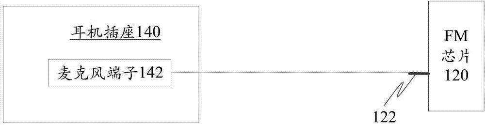
[0037] figure 1 It is a schematic circuit diagram of an antenna circuit shown according to an exemplary embodiment. The antenna circuit includes: FM chip 120 and earphone socket 140 .

[0038] The FM chip 120 includes an antenna interface 122 .

[0039] The earphone jack 140 includes a microphone terminal 142 .

[0040] The antenna interface 122 is electrically connected to the mic...


PUM


Abstract

The invention relates to an antenna circuit and a piece of electronic equipment, belonging to the field of electronic circuits. The antenna circuit comprises a FM chip and an earphone socket. The FM chip comprises an antenna interface. The earphone socket comprises a microphone terminal. The antenna interface and the microphone terminal are electrically connected. By using a microphone wire of an earphone as the antenna of the FM chip, the problem that antenna signals interfere with sound played in an earphone to reduce the sound quality of the earphone when a ground wire of the earphone is used as the antenna of the FM chip in the related technology is solved. Therefore, antenna signals do not interfere with sound played in the earphone, and the sound quality of the earphone is improved.

Description

technical field [0001] The present disclosure relates to the field of electronic circuits, in particular to an antenna circuit and electronic equipment. Background technique [0002] Radio functionality is a common feature found in electronic devices such as smartphones, tablets and e-book readers. [0003] In these electronic devices, an FM (Frequency Modulation, frequency modulation) chip is usually provided. The FM chip needs to cooperate with the corresponding antenna to work normally. Since the length of the antenna needs to be greater than 1 / 4 of the wavelength of the electromagnetic wave to be received, and the wavelength of the electromagnetic wave used in radio frequency modulation is relatively long, electronic devices usually cannot be directly set as the FM chip to set the antenna. In the related art, when using the radio function, the user needs to insert an earphone into the electronic device, and the electronic device uses the ground wire in the earphone as ...

Claims


Application Information

Patent Timeline
Patent Type & Authority Applications(China)
IPC IPC(8): H04R3/00
Inventor 孙伟底浩石新明
Owner XIAOMI INC
Why Eureka
Try Eureka