
Method, system and equipment for data transmission

A data transmission system and data transmission technology, applied in the field of data transmission methods, systems and equipment, can solve the problems of increasing scheduling delay, increasing switching signaling overhead, etc.

Active Publication Date: 2015-02-04
DATANG MOBILE COMM EQUIP CO LTD
View PDF5 Cites 28 Cited by
  • Summary
  • Abstract
  • Description
  • Claims
  • Application Information

AI Technical Summary

Problems solved by technology

If the data direct connection interface exists between the S-GW and the serving base station of the UE (that is, the data transmission path of the CoMP UE is still S-GWserving base stationUE), when the CCN selects the As the transmission point of the CoMP UE, the CCN needs to notify the serving base station to generate a Medium Access Control Packet Data Unit (MAC PDU), and then exchange the generated MAC PDU data packet to the transmission point selected by the CCN , which increases the scheduling delay of the UE on the network side
In addition, if the coordinating node is a small cell (such as a local base station (Local eNB)), and the CCN is a node that provides wide coverage (such as a macro base station (Macro eNB)), the movement of the UE may cause the UE to be in the service area of ​​the same CCN. Frequent switching between cooperative nodes increases switching signaling overhead

Method used


Image

  • Method, system and equipment for data transmission
  • Method, system and equipment for data transmission
  • Method, system and equipment for data transmission

Examples


Embodiment 1

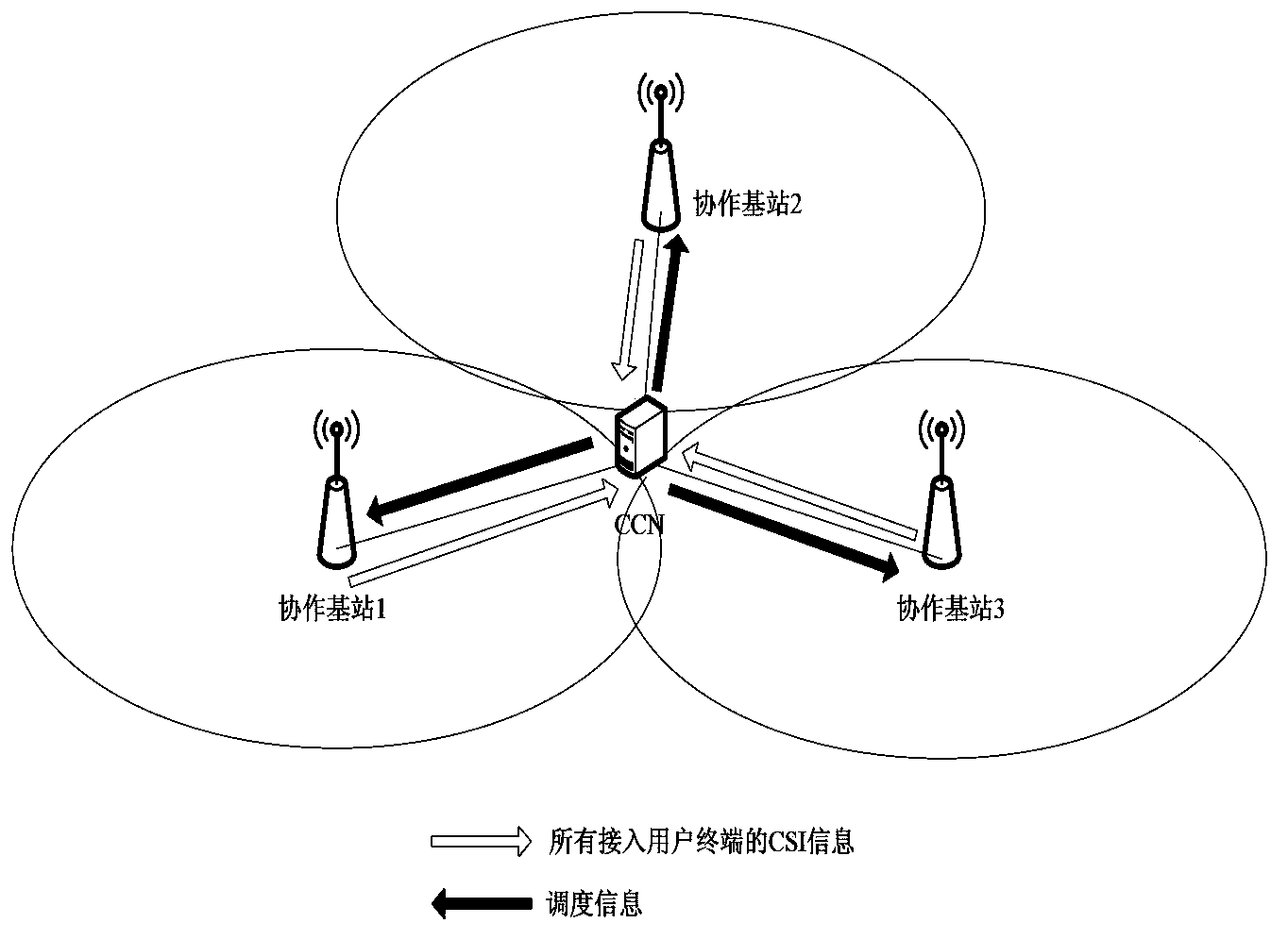
[0108] Such as Figure 4A and Figure 4B As shown in , a data transmission architecture in a non-ideal backhaul CoMP central scheduling scenario. Under this architecture, the data transmission path between the UE and the core network is S-GWserving base stationUE (that is, the data direct connection interface exists between the S-GW and the user's serving base station), and the CCN has the ability to CoMP UE scheduling control function, data temporary storage function and corresponding buffer.

[0109] Under this architecture, the data transmission path between the UE and the core network is still S-GWserving base stationUE (that is, the data direct connection interface exists between the S-GW and the user’s serving base station, and the CCN only has Scheduling control function, data temporary storage function and corresponding buffer for CoMP user terminals (CoMP user terminals refer to user terminals that include 2 or more transmission points in the measurement set). Non-C...

Embodiment 2

[0114] The CCN has a data temporary storage function, specifically including CoMP UE buffer settings, CoMP UE data interaction methods to be transmitted.

[0115] In order to reduce the impact of backhaul delay on data transmission, an independent buffer buffer can be set corresponding to each CoMP UE in the CCN. The CCN can set an independent buffer for each CoMP UE to store the data to be transmitted by the terminal; the size of the buffer buffer corresponding to each CoMP UE in the CCN can be the same (for example, the CCN can use information such as the load of all users / the amount of data to be transmitted, etc. Set the same buffer size for CoMP UEs according to the average value; or CCN pre-sets a fixed-size buffer to provide services for CoMP UE coordinated multi-point transmission), or it can be different (for example, CCN according to the user to be transmitted in the previous period of time) The data information of the CCN can be flexibly set to correspond to the buf...

Embodiment 3

[0131] The CCN schedules CoMP UE coordinated multi-point transmission and single-point transmission (single-point transmission means non-CoMP transmission). This solution is applicable to all CoMP transmission technologies (DPS / DPB, CS / CB, JT), and this embodiment only uses CS / CB transmission as an example.

[0132] The system assumes the following:

[0133]It is assumed that eNB1, eNB2, and eNB3 are coordinated base stations under the CCN. UE1 (CoMP UE, including base station 1 and base station 3 in the measurement set), the serving base station of UE2 is eNB1, UE3 (CoMP UE, including base station 2 and base station 3 in the measurement set), the serving base station of UE4 is eNB2, and the serving base station of UE5 is eNB3. Those not marked as CoMP user terminals are non-CoMP user terminals.

[0134] Step 1: All user terminals report CSI information, and each base station transmits the CSI information to the CCN through backhaul. The CCN obtains the data to be transmit...


PUM


Abstract

An embodiment of the invention discloses a method, a system and equipment for data transmission, relating to the field of wireless communication and used for reducing scheduling delay in a central coordination scheduling scheme under non-ideal backhaul. The method comprises the following steps that a CCN (Central Coordination Node) receives channel information of UE (User Equipment), which is transmitted by each coordinated base station; the CCN carries out CoMP (Coordinated-Multiple-Point) transmission scheduling of CoMP UE according to the received channel information of the UE, data to be transmitted of the CoMP UE, which is stored in a cache, and data size information to be transmitted of non-CoMP UE, and generates the scheduling information of the CoMP UE and an MAC PDU (Medium Access Control Packet Data Unit), which needs to be transmitted to the CoMP UE; the CCN transmits the generated scheduling information and the MAC PDU to each coordinated base station of the scheduled CoMP UE, and each coordinated base station carries out data transmission with the CoMP UE according to the received information. By adopting the scheme, the scheduling time delay of a network side on the UE is reduced.

Description

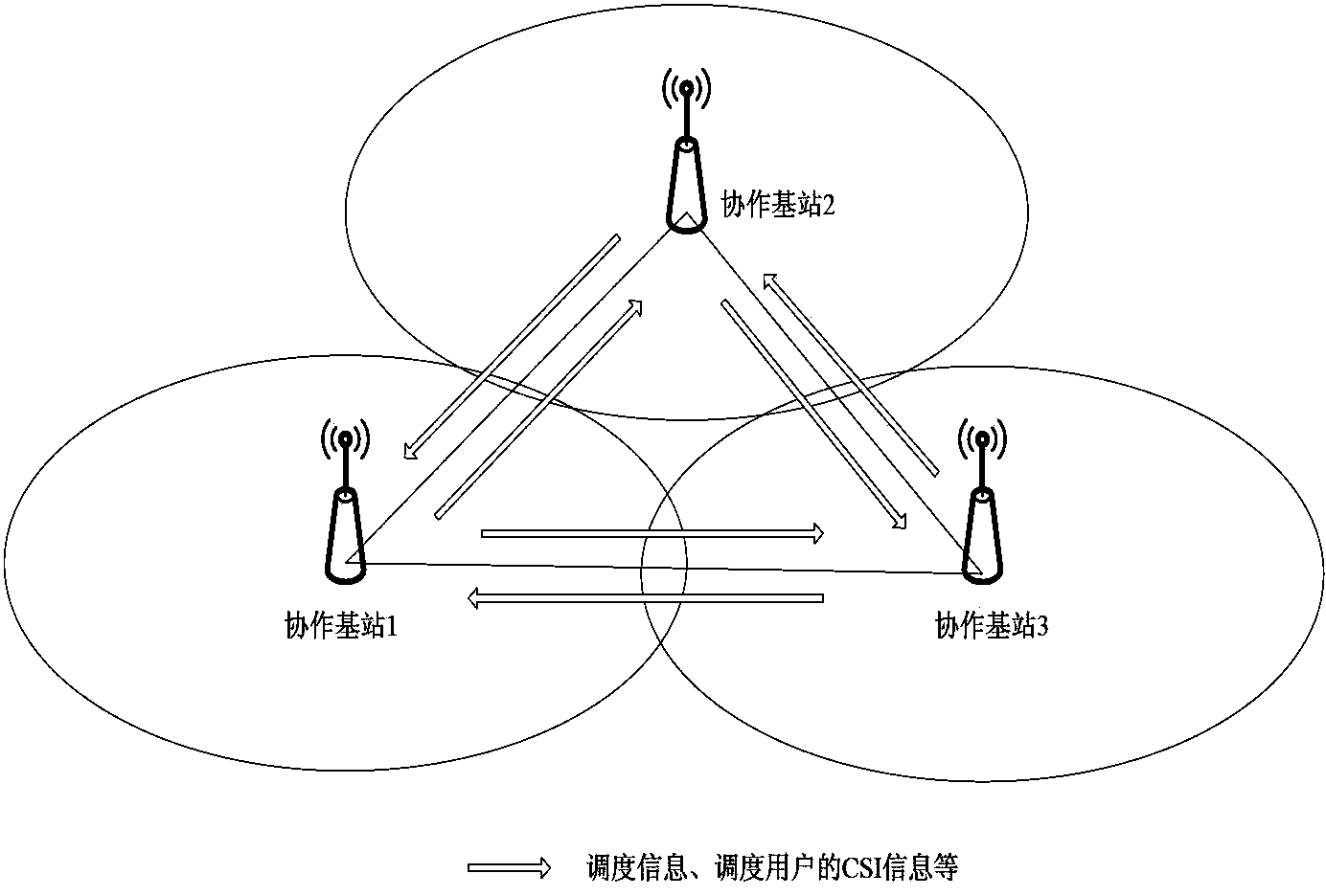
technical field [0001] The present invention relates to the field of wireless communication, in particular to a data transmission method, system and equipment. Background technique [0002] In order to reduce the interference of adjacent cells of user terminals at the edge of cell coverage and improve the experience of user terminals at the cell edge, the long term evolution-advance (LTE-A) system adopts Coordinated-Multiple-Point (CoMP) transmission technology. The coordinated multi-point transmission technology is the cooperation between multiple geographically separated transmission points (Transmission Point, TP), and the implementation of CoMP technology is divided into non-central cooperative scheduling based on whether there is a central node for global optimal scheduling. and central collaborative scheduling. Considering actual network conditions, Long Term Evolution-Advanced (LTE-A) Release 12 introduces a non-ideal backhaul link (backhaul) CoMP scenario. In the ...

Claims


Application Information

Patent Timeline
Patent Type & Authority Applications(China)
IPC IPC(8): H04W72/04H04W28/16
Inventor 付喆倪浩胡海静焦斌
Owner DATANG MOBILE COMM EQUIP CO LTD
Learn More