Totally-sealed cooling chamber

A heat-dissipating cavity, fully-sealed technology, applied in the direction of cooling/ventilation/heating transformation, can solve the problems of affecting the service life of the heat-dissipating cavity, leakage of cooling liquid, easy occurrence of gaps, etc., to achieve simple structure, good sealing, production short cycle effect

Active Publication Date: 2015-02-04
CHENGDU TIGER MICROWAVE TECH
View PDF9 Cites 1 Cited by
  • Summary
  • Abstract
  • Description
  • Claims
  • Application Information

AI Technical Summary

Problems solved by technology

This production method has the defects of long cycle, high cost and low reliability
After the heat dissipation cavity is used for a period of time, gaps are likely to appear between the upper cavity and the lower cavity, resulting in leakage of cooling liquid, which affects the service life of the heat dissipation cavity

Method used


Image

  • Totally-sealed cooling chamber
  • Totally-sealed cooling chamber
  • Totally-sealed cooling chamber

Examples


Embodiment Construction

[0019] The present invention will be further described below in conjunction with the accompanying drawings, but the protection scope of the present invention is not limited to the following description.

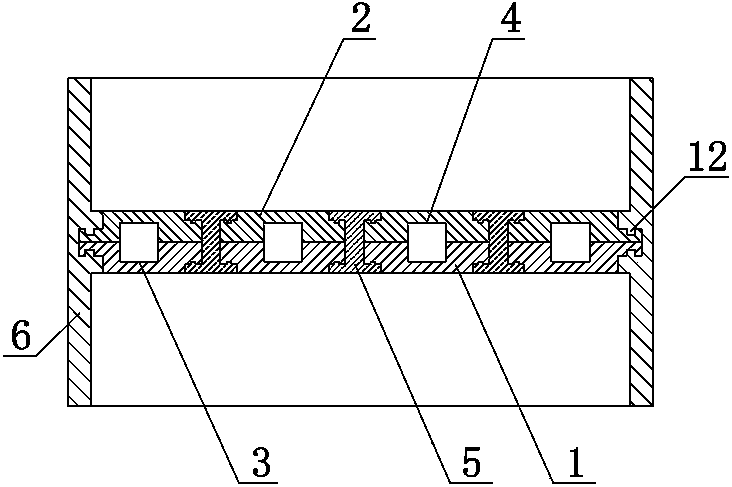
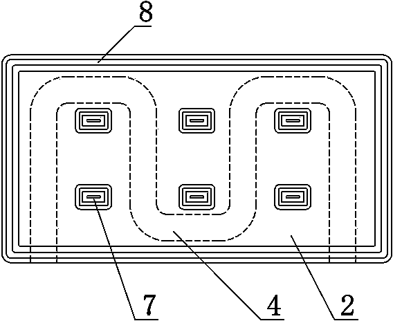
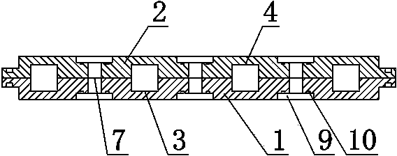
[0020] like figure 1 As shown, a fully-sealed heat dissipation cavity includes a lower cavity 1, an upper cavity 2, a locking block 5 and a reinforced enclosure 6, and a lower cavity cooling channel 3 is opened on the upper surface of the lower cavity 1. The lower surface of the upper cavity 2 is provided with an upper cavity cooling channel 4, and the lower cavity cooling channel 3 and the upper cavity cooling channel 4 are combined to form a cooling channel; the lower cavity 1 and the upper cavity 2 are respectively symmetrically provided with "T" shape hole 7, the two ends of "T" shape hole 7 are respectively provided with annular step surface 9, as figure 2 As shown, the "T"-shaped hole 7 is filled with aluminum alloy through die-casting mold and die-casting process to ...


PUM


Abstract

The invention relates to a totally-sealed cooling chamber. The totally-sealed cooling chamber comprises a lower chamber (1), an upper chamber (2), a locking block (5) and a reinforcing coaming (6), wherein a lower chamber cooling channel (3) is formed in the lower chamber (1), while an upper chamber cooling channel (4) is formed in the upper chamber (2); the lower chamber cooling channel (3) and the upper chamber cooling channel (4) are combined to form a cooling channel; a plurality of T-shaped holes (7) are symmetrically formed in the lower chamber (1) and the upper chamber (2), respectively; the T-shaped holes (7) are filled with an aluminum alloy by use of a die-casting die and a die-casting process so that locking blocks (5) can be formed; the lower chamber (1) and the upper chamber (2) are integrally and closely locked together by use of the locking blocks (5); the reinforcing coaming (6) is die-casted on the edges of the four sides of the lower chamber (1) and the upper chamber (2) by use of the die-casting die and the die-casting process. The totally-sealed cooling chamber has the advantages of good sealing effect, good inter-fusibility, short production period and suitability for large-batch production.

Description

technical field [0001] The invention relates to the technical field of manufacturing heat dissipation devices used in the working process of electronic components, in particular to a fully sealed heat dissipation cavity. Background technique [0002] Any electronic device has a certain loss during operation, and most of the loss becomes heat. Low-power devices have small losses and do not need a heat sink, while high-power devices have large losses. If no heat dissipation measures are taken, the temperature of the device may reach or exceed the allowable junction temperature, and the device will be damaged. Therefore, a heat dissipation device must be added. The most commonly used is to install the power device on the radiator, and use the radiator to dissipate the heat to the surrounding space. If necessary, add a cooling fan to enhance cooling and heat dissipation at a certain wind speed. Flowing cold water cooling plates are also used on the power devices of some large-s...

Claims


Application Information

Patent Timeline
Patent Type & Authority Applications(China)
IPC IPC(8): H05K7/20
Inventor 李先超
Owner CHENGDU TIGER MICROWAVE TECH
Why Eureka
Try Eureka