Supercharge Your Innovation With Domain-Expert AI Agents!

Variable geometry turbine

A turbine, geometric technology, used in mechanical equipment, engine components, engine manufacturing, etc., to solve problems such as pressure fluctuations or oscillations, and achieve easily predictable results

Active Publication Date: 2015-02-04
CUMMINS INC
View PDF7 Cites 2 Cited by
  • Summary
  • Abstract
  • Description
  • Claims
  • Application Information

AI Technical Summary

Problems solved by technology

In addition, there is a delay in the delivery of pressure through the pressure equalization holes, so there is a time lag in the delivery of pressure pulses from different engine cylinders, which will result in different positions on the nozzle ring Large pressure fluctuations or oscillations occur

Method used


Image

  • Variable geometry turbine
  • Variable geometry turbine
  • Variable geometry turbine

Examples


Embodiment Construction

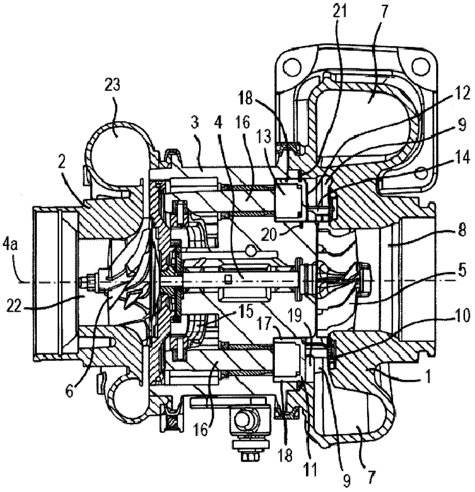
[0117] refer to figure 1 , which shows a known variable geometry turbocharger comprising a variable geometry turbine housing 1 and a compressor housing 2 interconnected with it via a central bearing housing 3 . The turbocharger shaft 4 extends from the turbine housing 1 through the bearing housing 3 to the compressor housing 2 . A turbine wheel 5 is mounted on one end of the shaft 4 for rotation inside the turbine housing 1 , and a compressor wheel 6 is mounted on the other end of the shaft 4 for rotation inside the compressor housing 2 . The shaft 4 rotates about a turbocharger axis 4 a on a bearing assembly located in the bearing housing 3 .

[0118] The turbine housing 1 defines an intake volute 7 and to which gas is delivered from an internal combustion engine (not shown). Exhaust gas flows from the intake volute 7 via the annular inlet passage 9 and the turbine wheel 5 to the axial outlet passage 8 . Said inlet passage 9 is delimited at one end by the radial wall surf...


PUM


Abstract

A variable geometry turbine has annular inlet passageway defined between a first surface of a radial wall of a movable wall mounted within a cavity and a facing wall of the turbine housing. The radial wall defines a second surface that opposes the first surface. The moveable wall member comprises an annular flange that extends axially into the cavity and supports a radial flange defining opposing third and fourth surfaces. The radial flange seals against an annular sleeve in the cavity to define a first area within the cavity which includes the radial second and third surfaces and a second area within the cavity which includes the radial fourth surface. The first and second areas are in fluid communication with regions of the annular inlet passageway which are respectively upstream and downstream of a radial vane passage.

Description

Background technique [0001] The present invention relates to a variable geometry turbine. [0002] As is well known, a turbocharger is a device for supplying air at a pressure above atmospheric pressure (boost) to the intake port of an internal combustion engine. A conventional turbocharger essentially consists of a turbine wheel driven by exhaust gases mounted on a rotatable shaft inside a turbine housing. Rotation of the turbine wheel turns the compressor wheel at the other end of the shaft mounted inside the compressor housing. The compressor wheel delivers compressed air to the engine intake manifold. Traditionally, turbocharger shafts are supported by journal bearings inside a center bearing housing connected between the turbine and compressor wheel housings, as well as thrust bearings, which also include a suitable lubrication system. [0003] The turbine stage of a conventional turbocharger includes: a turbine housing defining a turbine chamber housing a turbine whee...

Claims


Application Information

Patent Timeline
IPC IPC(8): F01D17/14F01D17/16
CPCF01D17/143F05D2220/40F05D2250/90F01D17/165F02B37/22Y02T10/12
Inventor 约翰·弗雷德里克·帕克西蒙·大卫·摩尔阿里·索菲娅
Owner CUMMINS INC
Features
  • R&D
  • Intellectual Property
  • Life Sciences
  • Materials
  • Tech Scout
  • Unparalleled Data Quality
  • Higher Quality Content
  • 60% Fewer Hallucinations
Learn More