Engine brake for vehicle

a technology for engine brakes and vehicles, applied in the direction of machines/engines, mechanical equipment, non-fuel substance addition to fuel, etc., can solve the problems of difficult control of such waste gates with desired accuracy, limited possibility of reducing epg to a desired size, and insufficient control of vgt with sufficient accuracy, etc., to achieve efficient flow control, improve control of the level of backpressure, and improve control of the effect of flow

Active Publication Date: 2010-04-29
VOLVO LASTVAGNAR AB
View PDF15 Cites 12 Cited by
  • Summary
  • Abstract
  • Description
  • Claims
  • Application Information

AI Technical Summary

Benefits of technology

[0034]The control system is intended to direct the flow to either of the main exhaust conduit or the bypass conduit. It would of course be possible to divide the flow into portions being guided to both conduits but the control of the exhaust backpressure is easier managed and the accuracy of the level of the backpressure is better regulated when the whole flow is guided to either one of the conduits.
[0035]There are several ways of controlling the flows of the exhaust stream. According to a first method, the control of the flows may be performed by the use of a first, main valve provided in the main exhaust conduit which may switch between being open

Problems solved by technology

This demand of the constructional aspects limits the possibility of reducing the EPG to a desired size.
The incorporation of a turbo compressor waste gate as a pressure regulator in this arrangement would also give rise to similar problems as for the EPG described in WO 95/26466.
Furthermore, it is usually hard to control such a waste gate with desired accuracy.
However, as in the case of the waste gate, the VGT is not easy to control with the sufficient accuracy to provide the desired back pressure, in particular when it shall have the ability to control the backpressure for a wide range of

Method used


Image

  • Engine brake for  vehicle
  • Engine brake for  vehicle

Examples


Embodiment Construction

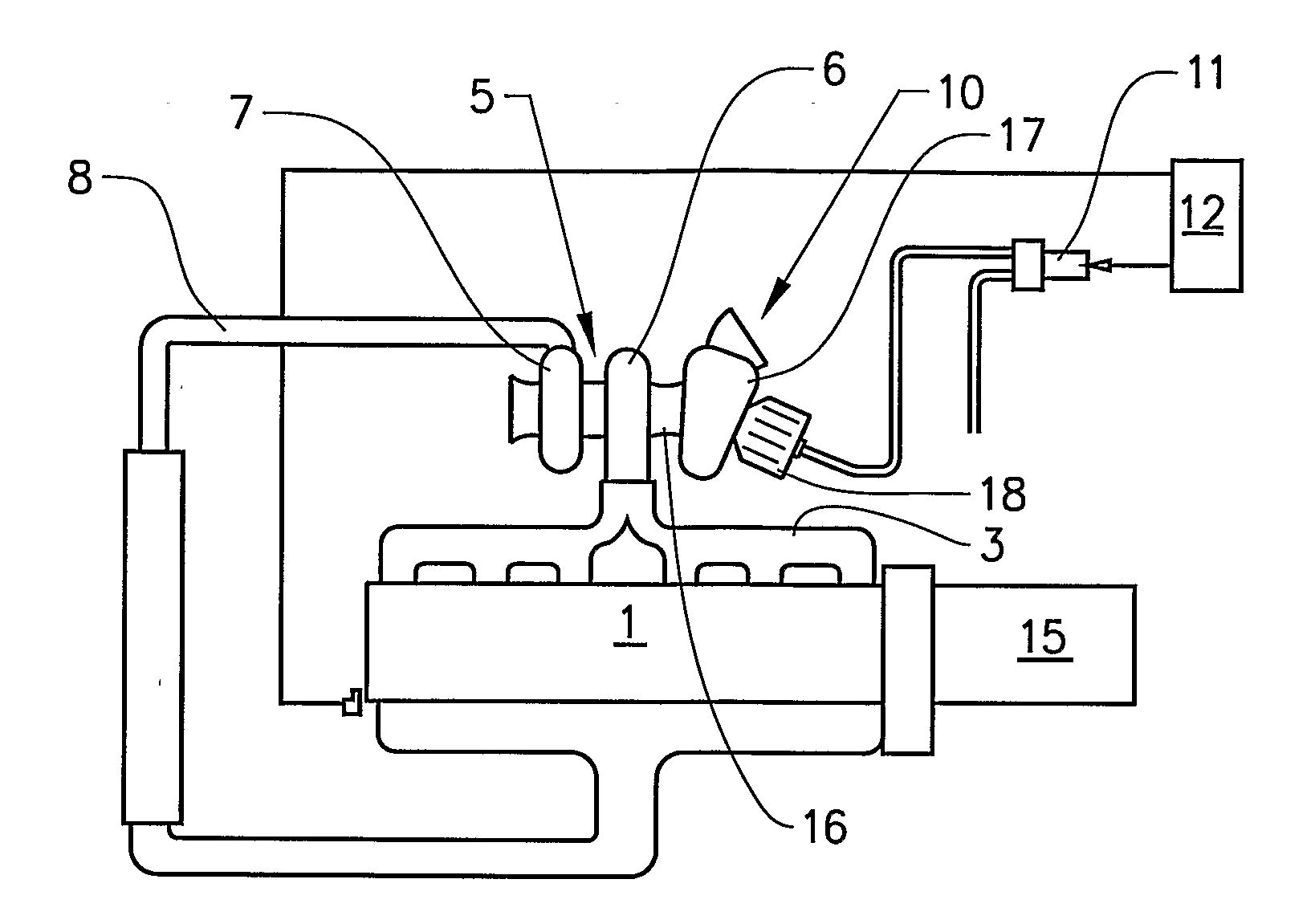
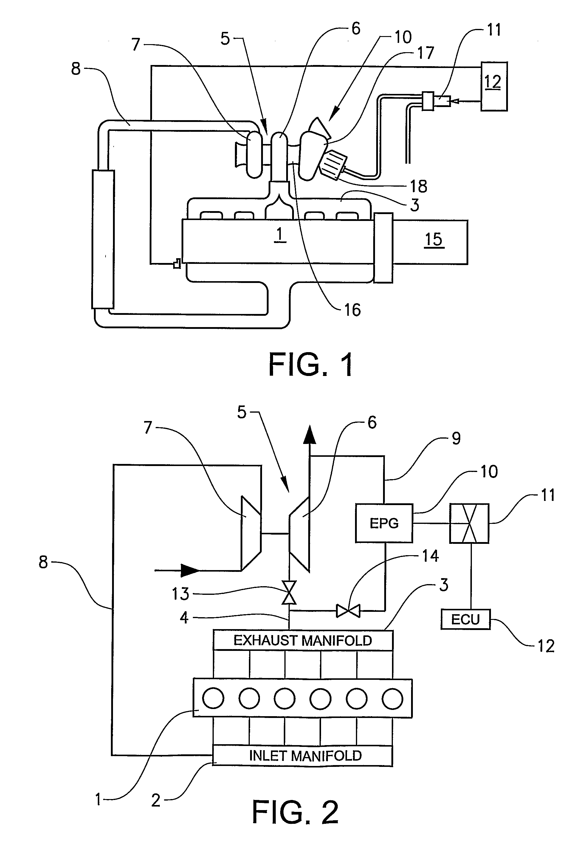
[0039]FIG. 2 shows schematically a six-cylinder diesel engine 1. The engine is provided with an inlet manifold 2 and an exhaust manifold 3. The exhaust manifold 3 is connected to a main exhaust gas conduit 4 which in turn is connected to a turbo assembly 5. The turbo assembly comprises a turbine portion 6 and a compressor portion 7. The turbine 6 is connected to the main exhaust conduit 4 and the compressor portion 7 is connected to an air intake conduit 8 which in turn is connected to the inlet manifold 2. The main exhaust gas conduit 4 is further connected to a bypass conduit 9 downstream the exhaust manifold 3 and upstream the turbo assembly 5. An Exhaust Pressure Governor (EPG) 10 is located in the bypass conduit. The EPG 10 is connected to air pressure control valve 11 for regulating the air pressure from a source of compressed air (not shown). The control valve 11 is further connected to an Electronic Control Unit (ECU) 12 which provides output signals for turning the compress...


PUM


Abstract

An engine brake system and a method for controlling the exhaust gas pressure of an exhaust system for a vehicle provided with an engine are provided. The system includes a main exhaust gas conduit connected to the turbine of a turbo arrangement and an Exhaust Pressure Governor (EPG) which is used to create a backpressure in the exhaust system so as to function as an engine brake. The turbo arrangement includes a Variable Geometry Turbine (VGT). The Exhaust Pressure Governor is located in a bypass conduit which is connected to the main exhaust conduit upstream the connection to the turbine of the turbo arrangement and the main exhaust conduit includes a valve arrangement downstream the bypass conduit connection for closing the main exhaust conduit. According to the method for controlling the system, the flow passage through the main conduit is open and the flow through the bypass conduit is closed in response to an output control indicating that no engine braking is desired. In case there is an output control indicating that engine braking is desired, the flow passage through the main conduit is closed and the flow through the bypass conduit is open whereby the EPG is controlled to provide a desired backpressure according to the control signals from the control system.

Description

BACKGROUND AND SUMMARY[0001]The invention relates to an engine brake for a vehicle in general and in particular to the arrangement of an Exhaust Pressure Governor (EPG) working as an engine brake in an engine provided with a turbo compressor comprising a Variable Geometry Turbine (VGT). The invention also relates to a method for controlling an engine brake operation and an exhaust gas pressure.[0002]The use of engine brakes in general and Exhaust Pressure Governors (EPG) for controlling the engine braking power of an internal combustion engine in a motor vehicle is known in the art. Details of such an arrangement are for example disclosed in WO 95 / 26466. This device includes a control unit which includes a microprocessor, to which there is fed relevant engine data and vehicle data for computing and continuously varying the degree of charging, so that the retardation of the vehicle during braking can be controlled towards a command value set by the driver.[0003]With reference to FIG....

Claims


Application Information

Patent Timeline
IPC IPC(8): F02D9/06F02D23/00
CPCF01N2240/36F02B3/06F02B29/0406F02B37/02Y02T10/144F02B37/22F02D9/06F02M25/0706F02B37/18F02M26/04Y02T10/12
Inventor CARLSTROM, PETERLARSSON, PER
Owner VOLVO LASTVAGNAR AB
Why Eureka
Try Eureka